Seamless data flow from propulsion to power plant, and higher-level advisory services onboard and ashore offer new possibilities for the optimal use of information.
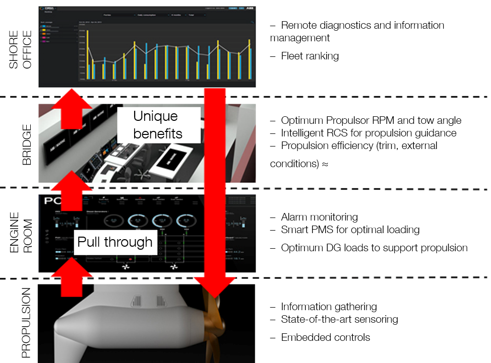
.The current way of operating the vessel can be improved at many levels to increase the overall operational efficiency. However, to identify what needs to be changed, the current performance and its weakest points must be understood. This depends on everyone on board being familiar with the key elements affecting performance – from engine room technical staff to the crew on the bridge and operations staff at the shore office.
Figure 2 shows vertical integration in a total propulsion solution [HK1]. The various elements and features of the solution will then be discussed.
Azipod® Propulsion
An azimuthing electric propulsion and thruster system has a variable speed electric motor inside a submerged pod that drives the fixed pitch propeller. The pod can be rotated 360 degrees around its vertical axis.

If a vessel is equipped with two or more Azipod propulsion modules, ABB offers an Azipod dynamic optimizer (ADO) tool for the towing angle of the Azipods. This requires constant measurement of the real conditions. The system is totally automatic, constantly providing the optimum thrust for the vessel.
Azipod propulsion also enables efficient and reliable monitoring of various data. This includes the shaft-line bearings’ vibration level, which is indicated to the vessel operator on the bridge. Sample-based oil analysis rounds out the condition status evaluation by providing information about the quality of oil samples taken from various pieces of equipment.

Propulsion control
Controller hardware and software are designed for safe operation in all conditions, as well as for high dynamic performance. Optional control parameters are flexibly programmable according to special requirements.
The engineer in the engine room has access to the entire automation and propulsion system. This includes:
Propulsion power breakdown
One of the fundamental problems related to vessel operational costs is determining the work required to move a vessel from one point to another. This is a complex problem due to the many different physical phenomena acting on a vessel.In general, the goal of a vessel is to move from point A to point B in a fixed reference frame – the Earth Centered Rotational (ECR) Cartesian coordinate system. However, the movement of the vessel takes place in two other reference frames, which change both with respect to the fixed frame and themselves. The moving frames are the media the vessel has to move through the sea and the atmosphere. The combination of these three coordinate systems form a common framework where the current power demand required to advance the vessel and its distribution can be determined at any given time.
The power required at any given time for the vessel to move can be broken down into two parts. The first component describes the power required to move through the media and the second describes the virtual power related to the changes in the sea medium frame with respect to the fixed coordinate frame. By denoting the components as powers related to the speed over ground (SOG), speed through water (STW) and sea current, the following relation can be defined:

where PSOG(t) is the power required to move the vessel with respect to the ECR frame, PSWT(t) is the power required to move the vessel through the water and air and Pcurrent(t) is the virtual power produced or consumed by the sea current.
The power required to propel the vessel through the sea and air can be further broken down to several subcomponents that may vary depending on vessel type. This breakdown can be expressed as:

– Engineer in engine room has access to entire automation and propulsion system
– Local and remote control
– Operational modes and control modes
– Protection functions
– Blackout protection
– Operational limitations
– Auxiliary device control
– Start interlocks
where the subscript i denotes the different power components related to the movement through water. Pwind(t) is the power produced or consumed by the movement of the lesser density medium (atmosphere) frame with respect to the higher density medium frame (sea) – that is, the wind power.
The power components related to the movement through water depend on the vessel type. The typical components include such phenomena as draft, squatting, rudder usage, stabilizer usage, propelling effort, the floating position of the vessel, the dominant sea state and other factors.
The different components can be described as follows:
– Draft – changes in the hydrodynamic drag due to the changes in the vessel draft.
– Squatting – additional power required in the shallow waters, where the power required to displace the water is increased.
– Rudder usage – additional drag due to the rudder angle of attack.
– Stabilizer usage – additional drag due to the stabilizer fin angles of attack.
– Propelling effort – power required to overcome both the hydrodynamic resistance of the vessel and vessel inertia.
– Floating position – additional power required for moving the vessel due to suboptimal trimming and listing of the vessel, that is, to overcome the impact of the increased hull resistance and inefficient orientation of the propulsion water flow field.
– Sea state – additional power required to overcome the impact of the rough seas such as high waves slamming the vessel.
– Other factors that contribute to unidentifiable phenomena such as the hydrodynamics of the media itself.

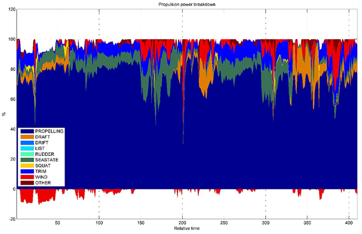
Typical actions that can be taken by the crew include trimming the vessel for a more optimal attitude and changing heading to minimize the impact of the wind and sea state losses, assuming that the deviations from the original route are permitted. The vessel operator can take several different actions based on the time series data. The route plans and schedules may be altered to avoid circumstances where the vessel is constantly going against currents, tides and prevailing winds. The vessel loading can be re-planned such that it is in accordance with the optimal draft for the intended operation profile. In addition, the power distribution time series provides a transparent view for monitoring the overall performance of the vessel.
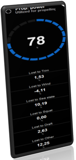
The realized shaft-power breakdown time series collected onboard a vessel with the EMMA™ Onboard Tracker system installed is illustrated in Figure 4. According to the figure, it is apparent that significant savings could be obtained simply by changing the attitude of the vessel. In addition, the impact of the wind and sea state is clearly distinguishable. The negative wind powers indicate that the vessel hull is acting as a sail and the vessel is actually being pushed forward by the wind, thereby saving energy.
In conclusion, the power breakdown monitoring system is a good example of a system that uses the information obtained from all levels of the vessel and extracts some new physical quantities. These quantities provide additional information about phenomena that are not directly measurable, yet have a significant impact on the vessel’s performance and its energy efficiency.

Power management system (PMS)

The ABB PMS is based on the 800xA Industrial Extended Automation System. The main task of the PMS system is to ensure a balance between power consumption and power production, thus keeping the electrical network as stable as possible. In practice this is done by controlling the electrical power production resources as well as controlling the usage of large consumers.
There are many ways to produce electrical power on ships. In diesel-electric vessels, the most common means nowadays is to have, for example, four diesel generators, two of which can be of different sizes. In the cruise and ferry segment, the most complex power plants are in hybrid vessels that have triple-fuel main engines with generators and steam turbine waste heat recovery systems (WHRS) as well as energy storage systems. Energy storage systems make the operation of the power plant significantly more challenging, because energy storage introduces new kinds of dynamics in the power plant. Significant fuel savings can be achieved by smart control of the power plant with a WHRS and energy storage.
The ABB PMS integrated with the EMMA™ Advanced Power Plant Optimizer is designed to optimize operation of the power plant by taking into account the current and future power demand and the operation mode. Integration with the ABB Propulsion Control System (PCS) supports optimal power plant operation even further by providing information about the expected rapid load variations in the propulsion system based on the movements of the control levers.
The levels of vertical integration during optimal operation of the ship power plant are described in Figure 6. At the highest level, the information about future operating conditions such as weather, sea state, ambient conditions, etc. is obtained from forecast databases. These are used in route planning and ship speed optimization for just-in-time arrival.
The EMMA™ Onboard Tracker uses state-of-the art databased modeling methodologies to create nonlinear regression models for all types of performance and input variables. By using the EMMA™ model learning engine, the electrical power demand with respect to the operating conditions can be easily calculated and predicted. Consider operating conditions such as ambient temperature, seawater temperature, ambient relative humidity, amount of people onboard, local time of day, amount of cargo/containers, etc. at time t to be denoted by θAUX(t) and the auxiliary electrical power demand at t by PAUX(t)(kW). Based on data collected on board the ship during normal operation, the EMMA™ modeling engine finds a nonlinear model

that predicts the auxiliary electrical power demand as accurately as possible, based on the input data. The model learning is automatic and requires no action from the end user of the system. The modeling algorithm can automatically determine the relevance of each input signal in predicting the output value, and if some input signal has no effect on the input signal, the algorithm removes it from the model. Once the model has been trained the required auxiliary electrical power can be effectively forecast based on the weather forecasts and route information.
As with the auxiliary power demand, the required electrical or mechanical power for propulsion can automatically be forecast using EMMA™ tools as previously described. The total electrical power demand at t is then calculated using

Optimal power plant usage required predictive planning of the use of the power plant resources over the short and long term. In the short term, the rapid propulsion power variations should particularly be taken into account in the optimization. Depending on the operation mode, the required spinning reserve (the maximum available power with the currently running engines/resources) varies. During maneuvering, the spinning reserve should be larger than during the sea passage.
The vertical integration in the PCS, PMS and EMMA™ power plant optimization module enables the optimization of the power plant operation so that the operation modes and short-term power demands (1–60s) can be fulfilled. Moreover, by planning the use of the power plant resources further ahead in the future (3–24h), the unnecessary starting and stopping of engines is avoided and optimal use of energy storages and WHRS systems are guaranteed.
The integration of the ABB PMS, Diesel Generator Maintenance System (DGMS) and EMMA™ power plant optimization enables the inclusion of information about safety constraints and faults that resources that are not functioning properly are not taken into account in the optimization.
Depending on the customer’s needs, EMMA™ power plant optimization can be used in real time to find the optimal load balance based on the current power demand or to optimize the use of resources within a longer time horizon. Already momentary load balance optimization enables yearly savings of about 1.5 percent in fuel consumption for a typical operation profile of a large cruise ship. By taking into account the long-term forecasts, especially in complex power plants with WHRS and energy storage, the savings potential is significantly larger.

Figure 6 Levels of vertical integration during optimal operation of a ship’s power plant 
Figure 7 Screenshot of the ABB power plant optimization advisory screen 
Figure 8 The Red Dot Award winning ABB azimuth lever
Vertical integration in the ABB PMS and EMMA™ enables automatic use of the power plant optimization result in the PMS so that starting and stopping and the load balance between resources is performed automatically. The PMS takes care of the necessary safety limits and can reject the optimization result if it does not conform to the safety criteria.
The ABB power plant optimizer uses specific fuel oil consumption (SFOC) or other characteristic curves adjusted with statistical data from real life measurements. EMMA™ Onboard Tracker calculates the real-time SFOC value based on the measured volume/mass flow of the net fuel flow consumer by each diesel generator. EMMA™ is able to calculate the fuel mass flow based on the volume flow, temperature and fuel type by using the ASTM D 1250-04 standard methods. In addition, the electrical power produced by each generator is measured. With EMMA™, the variation due to external conditions in the measured SFOC values is compensated for by using the ISO 3046-1:2002(E) standard methods. The SFOC/characteristic curves of each resource are combined into a networked flow optimization problem, which is solved by ABB energy management technology designed for controlling smart grids.
ABB power plant optimization allows the user to determine and change the required spinning reserve as well as the operation limits for each power producer. Moreover, the user can exclude some resources from the optimization model in real time.
The system is also able to take into account the maintenance cycles of the power producers. Depending on the customer requirements, the optimization can be done based only on the current information or, additionally, by taking into account the future power demand, which allows the system to use the MPC (Model Predictive Control) philosophy.
Intelligent maneuvering on the bridge

Think about a system failure within a complex automation system when operating tight routes in, for example the Archipelago Sea off Finland. Troubleshooting to solve such a situation requires only necessary information in the right place or guidance for optimal decision making in minimized time. Unnecessary system alarms can violate safe operation.
The recognition of a wide range of use situations is crucial in the development of automation systems. User-centered requirements with easy and simplified user interfaces enable the right architecture for integrated automation systems to serve the operator.
ABB Marine is cooperating with customers and end users in their research and development processes. Means and methodologies of industrial design such as concept workshops, visual communication and physical demonstration prototypes at an early phase in the process enable customer to experience the product functionalities and features. In addition, this helps to anticipate forthcoming problems and bottlenecks within the systems, which in turn allows inexpensive changes and more customer orientation in the project.
Bridge personnel can control propulsion via a remote control system. Smart remote control systems also warn about the wrong use of propulsors resulting in excess vibration and associated maintenance costs.
Shore asset and performance monitoring
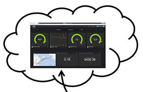
All the data collected and calculated on board is automatically transferred to an online performance data analysis tool. EMMA™ Fleet Control is built with a high cyber security Azure Cloud service by Microsoft. This enables secure data access at any locations for the shipowner. EMMA™’s centralized database is used to form baseline and ranking of the fleet performance. This benchmarking data is replicated back to the vessels so that fleet-wide performance is visible to onboard users without a broadband connection.
Typically, the captain selects a speed somewhat above the required average speed to ensure that the ship will arrive on time. The speed/power curve of the ship is exponential and it is very expensive to exceed the required speed. By smart speed selection, the fuel saving can be significant.
ABB speed optimization calculates the optimal RPM in the cloud service and advises the officers on board on the optimum speed or RPM to reach the ETA with desired buffer time and taking the weather into account.
The speed is set on board as speed through water by adjusting the engine power or engine RPM. The actual speed of the ship is a combination of this and environmental conditions (weather, current, water depth and wave / swell height / direction / period).
Remote Diagnostics

Figure 10 RDS4Marine is a diagnostic tool providing troubleshooting and condition monitoring solutions for electrical and mechanical systems installed on board with remote assistance from the Global 24/7 Technical Support Center. 
Remote diagnostics give instant access to data, which helps in the planning of preventative maintenance. A service engineer will carry out planned maintenance operations based on monitoring data collected. Preventive maintenance saves service costs as service can be planned to suit the vessel’s docking schedule in the best possible way.
Power of integration unleashed
As described, through fully integrated propulsion, ABB’s complete solution unleashes the real power of integration. When the ship is equipped with ABB Azipod, automation system, power management and decision support tools, the information flow is not only enabled but significantly simplified. The more the system knows, the more it is able to efficiently advise on operations and save money.