CuiYun Li, Harry-ZhiMin Sun, QuanHong Zhou ABB Beijing Drive Systems, Beijing, China, cuiyun.li@cn.abb.com, harry-zhimin.sun@cn.abb.com,quanhong.zhou@cn.abb.com; Rick-RuiXue Jiang,Nicole-Jie Huang, Cathy-lina Han ABB Shanghai Motor Systems, Shanghai, China, rick-ruixue.jiang@cn.abb.com, nicole-jie.huang@cn.abb.com, cathy-lina.han1@cn.abb.com; Darren Tremelling, Ghanshyam Shrestha ABB Low-voltage IEC Motors, Cary, NC, United States, darren.tremelling@us.abb.com, ghanshyam.shrestha@us.abb.com; Matti Laitinen ABB Motion, Helsinki, Finland, matti.laitinen@fi.abb.com
Due to the increasing need for greater power density, better efficiency and tolerance of higher temperatures in electric drive systems, more users are turning to IMDs. IMDs also reduce costs: By eliminating separate enclosures for the motor and drive and taking away long cable runs, the integrated approach can lower system costs substantially. The removal of cables and the associated electromagnetic noise filters also increases reliability.
Further, integration of drive and motor significantly improves the device’s electromagnetic compatibility (EMC) characteristics and allows EMC testing and prevention measures to be applied to the complete package at the point of manufacture. In addition, testing and commissioning is faster when just a single unit is involved. Automation of manufacturing is made easier, too.
Users are grateful for the space freed up by the IMD system’s smaller size compared to a traditional, separated solution. For example, inverter control rooms and associated ventilation equipment are no longer needed as the integrated motor and drive can utilize a single cooling system, reducing both system footprint and cost.
IMDs for 7.5 kW
Technological advances over the last decade have produced robust electronic components better able to withstand the rigors of IMD integration. However, to reap the benefits of the IMD approach described here, careful thought must be given to the electrical, structural and thermal implications of combining different elements into a single package.
Existing examples of advanced motor cooling display a targeted approach for removing heat directly from individual heat sources by, for example, indirect stator-winding heat-exchanger cooling or stator-winding heat-guide transport. These techniques of focused thermal management aimed at specific heat sources are enabled by additive manufacturing, highly integrated heat exchangers, multi-functional composite materials, phase-change heat transport and storage and thermal pads. However, such methods are insufficient to solve the challenges faced by high-performance IMDs – for example, the issue that thermal build-up from the motor, electronics and drive presents a practical limit for the operation of drives rated at over 7.5 kW. The physical size of the AC/DC converter also constrains the power rating of commercial IMD units. Above the 7.5 kW threshold, traditional separated motor-drive systems usually offer a better alternative, hence the dearth of high-power commercially available IMDs.
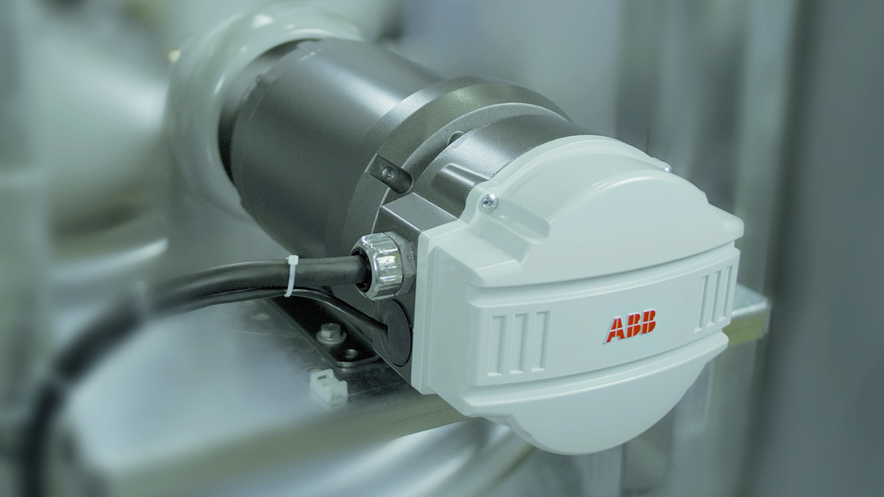
ABB has now successfully developed 7.5 kW IMD prototypes that exhibit excellent performance – especially in terms of thermal management and low radiated electromagnetic emissions →01. These devices have already received positive customer feedback.
End-plate-mount integration
Despite significant awareness of IMDs in industry and extensive research and literature on the subject, very little work exists on complete power electronics and machine integration. That which does exist can be divided into three categories: surface-mount integration, stator-iron-mount integration and end-plate-mount integration. For various reasons, such as the stable mechanical platform it provides for the AC/DC convertor, ABB has focused on the latter configuration as a basis for the new IMD design.
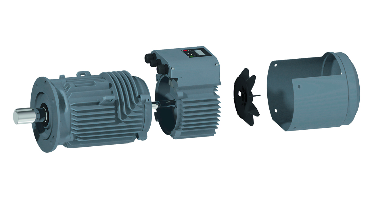
Mechanical structure of the new IMD approach
The new IMDs are designed with a shaft height of 90 mm, down from the conventional 132 mm. This compactness reduces the surface area available for heat dissipation and halves the surface area of the non-drive end plate that is available for drive component placement. This situation created a challenge for cooling and packaging the IMD. Here, the concept of an end-plate-mounted drive where the drive is placed between the motor and the fan, together with the new mechanical design of the frame, mitigates thermal issues and saves space →02. An optimized printed-circuit board (PCB) assembly layout saves further space. A pluggable connection cable between the drive and motor means either can be replaced separately and maintenance is simple.

03a Shaft sealing. 
03b Gaskets seal cable termination points and circuitry.
03 An IP56 rating is attained through effective sealing.
To achieve an IP56 rating, the rotating shaft is sealed at each end →03a. These seals are of a standard design for ease of sourcing. Cables pass through glands and the space in which their termination blocks are located is sealed by a gasket →03b. The junction box cover is designed with integrated buttons and a gasket between the junction box cover and drive frame →03b.
A total thermal management concept
Thermally, the machine suffers because cooling is restricted by the end-plate design; all end-winding losses must now be conducted radially. Therefore, mechanical and cooling aspects must be considered as a whole. Here, heat conduction between the AC/DC convertor and motor and heat dissipation from these two elements are critical factors →04.
An initial thermal design was established and tested with positive results. This design was then enhanced in a second development cycle.
Initial thermal design
Today, devices based on silicon are the dominant power semiconductor choice. However, due to basic physical restrictions, these devices have reached their limits in terms of further development and downscaling. They also have a maximum temperature for the device junction in the range of 125 to 150 °C.
Because of these restrictions, ABB’s new IMD approach uses devices based on silicon carbide (SiC) semiconductor technology. SiC is a good choice when performance requirements are very demanding. For example, SiC devices typically have low power losses at the high frequencies that permit smaller components and a consequent reduction in equipment volume. SiC also has a higher thermal conductivity than silicon, so quickly conducts heat to its surroundings.
The device’s capacitors, relays, chokes, etc., also generate considerable heat. This heat flows via thermal pads and thermal grease to a heatsink for removal by the airflow produced by the specially designed fan. The IMD design discussed here represents the first time thermal pads have been used in an ABB drive.
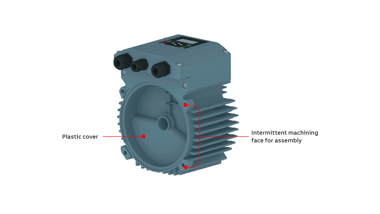
The optimal shape for the heatsink and motor cooling fins was determined by extensive thermal simulations. The surface of the heatsink is coated to meet environmental requirements. Further, the sealed nature of the enclosure isolates internal electronic components from any external corrosive gas that may be present. So-called intermittent machining of the inverter/motor touching faces introduces a roughness that ensures reliable fixation – vital for the coaxial elements – and reduces the metal contact area, minimizing heat conduction →05.
Enhanced design
Although the IMD described above is compact and performs well, it presents heat dissipation challenges. The frame can reach 86.9 °C at an ambient temperature of 35 °C, exceeding the customer’s maximum spot temperature requirement of 80 °C. The customer also expects the IMD to have a more pronounced energy-saving effect. Therefore, ABB improved the mechanical strategy to boost dissipation and enhanced the electromagnetic design to reduce heat generation and save energy.
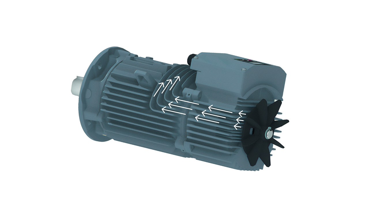
As a first step in this enhancement exercise, matching ribs were integrated into the metal shells to give a high-efficiency cooling structure →06. Combined axial and radial ribs are used for the motor stator frame, optimizing the cooling air path →07.
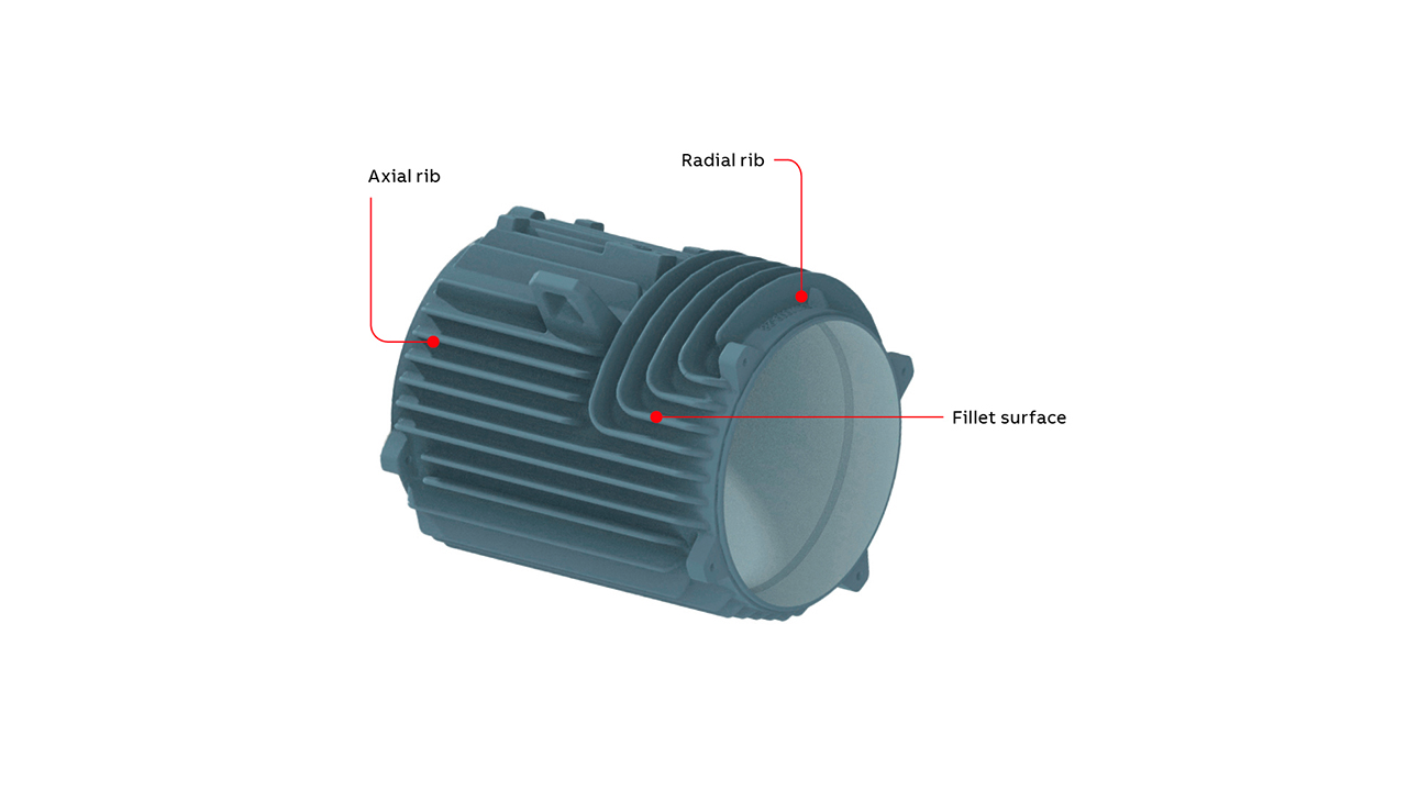
The next step was to use computational fluid dynamics (CFD) to optimize the motor frame and thus reduce housing temperature. Subsequently, electromagnetic optimization reduced the frame temperature rise and improved the overall IMD efficiency while remaining within overall volume limitations.
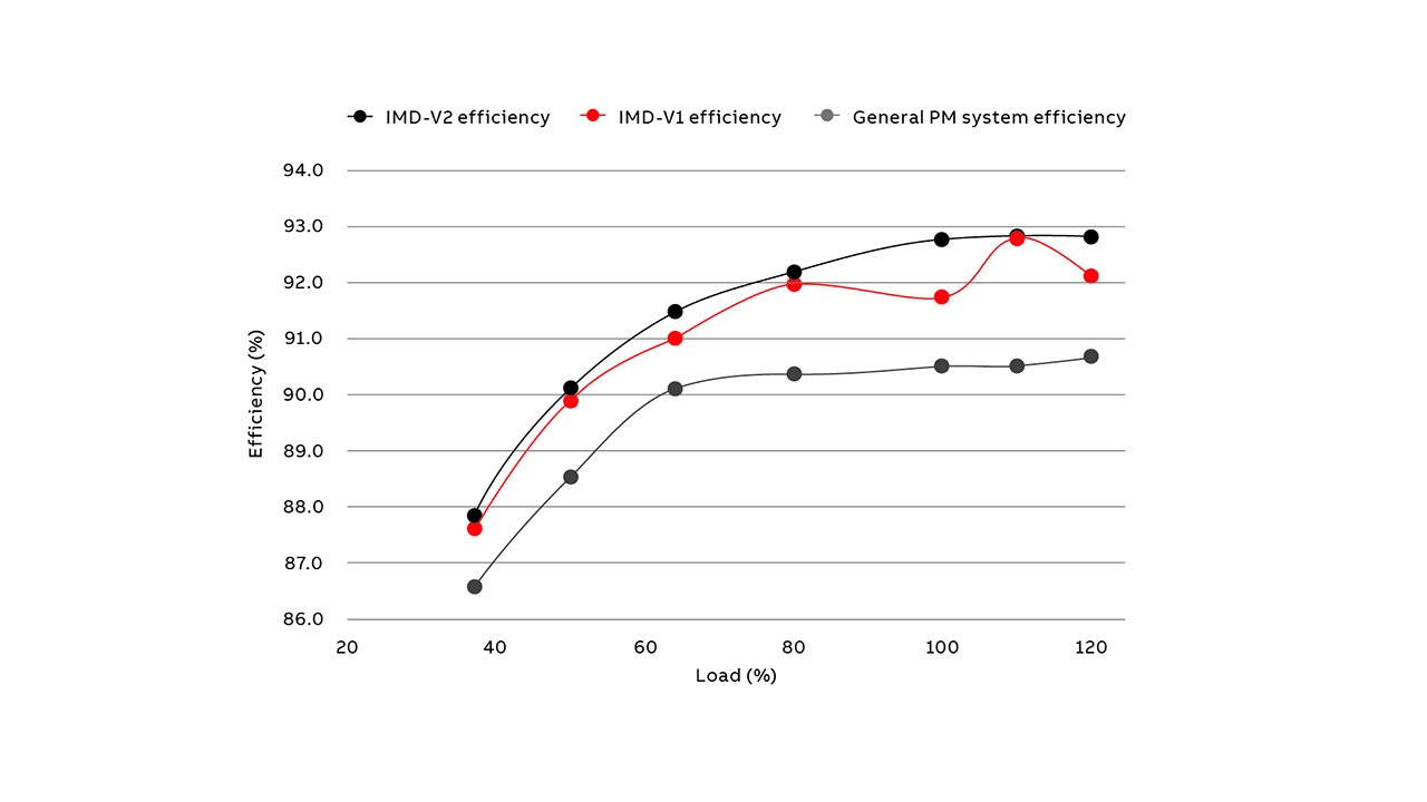
These measures achieved the customer requirement that the maximum temperature at any point on the frame should be below 80 °C at an ambient temperature of 35 °C. Indeed, the frame temperature is lower than that of ordinary permanent magnet motors, while the efficiency is higher →08.
In this design, silicon insulated-gate bipolar transistors (IGBTs) were used to keep costs down, with a view to later utilize SiC devices once they become less expensive.
Driving future development
The thermal, mechanical and electromagnetic designs realized in the IMD described above offer significant cost and performance benefits for high-power applications. Further work should address the relatively high price of SiC devices, which are around three times as expensive as their silicon counterparts, and ways to ameliorate the effects of higher operating temperatures on other system components, such as capacitors. The rapid response times of SiC devices to short-circuit-type events and consequent false triggering is another topic that merits closer investigation. Finally, ABB has initiated collaboration with vendors to align SiC module packaging with ABB’s particular needs.
