ABB applied advances in numerical software to additive manufacturing technology to create powerful solutions for the 3D printing process that optimize and improve the design of essential components, while reducing overall costs.
Lukasz Matysiak, Tomasz Nowak, Robert Sekula, Dariusz Bednarowski ABB Corporate Research Krakow, Poland, lukasz.matysiak@pl.abb.com, tomasz.nowak@pl.abb.com, robert.sekula@pl.abb.com, dariusz.bednarowski@pl.abb.com; Frederic Tholence, Erik X. Johansson ABB Corporate Research Västerås, Sweden, frederic.tholence@se.abb.com, erik.x.johansson@se.abb.com; Peter Schuster ABB Technology Center Uster, Switzerland, peter.schuster@ch.abb.com
During the last decade, rapid progress has been made in Additive Manufacturing technology (AM), also known as 3D printing: the manufacture of parts by adding material in a layer-by-layer process [1]. Scores of AM processes fabricate metallic or polymeric parts; utilize different combinations of stock material forms, deliver varied materials and employ various heat sources. The family of material extrusion processes (Fused Deposition Modelling or Fused Filament Fabrication) is an important example. Relying on the original filament form, objects are built by the selective deposition of a melted thermoplastic polymer. This contrasts with powder-based processes (using metallic or polymeric powder) in which powder is spread onto the apparatus base before it is scanned or fed directly to the heat affected region.
Thanks to these advances, AM provides manufacturers with freedom in design and the ability to build (3D print) an assembly composed of multiply integrated parts.
Nevertheless, the inherently complex processes pose obstacles that can impede the broader application of AM. For instance, product geometry and material structures, which are defined during the AM process, pose complex constraints. Additionally, the process itself can influence the material deposited during this manufacturing technique in which a single layer is “cast” upon a previous layer. The combined effects of rapid solidification, directional cooling, and phase transformations induced by repeated thermal cycles can adversely impact the microstructures of the material deposited. Moreover, the produced parts may not comply with the mechanical requirements due to unacceptable porosity levels. The thermo-mechanical nature of the process can result in serious dimensional inaccuracies: the result of thermally induced residual stresses and distortions [2].
Not surprisingly, numerical engineering tools, eg, finite element analysis software packages, reveal physical phenomena that are critical. In this way, engineers can understand the link between the product design, process settings, material microstructure and physical properties of the 3D-printed products. Numerical tools are also very effective in parametric and topology optimization methods, where the aims are to reduce the weight of the component and to optimize the printing time.
ABB case studies
ABB evaluated engineering tools and numerical simulations in three case studies to determine specific instances where AM applications offer customers value beyond the advantage of design freedom. Toward this end, the perceived drawbacks of AM – long printing times and high costs – were addressed:
• Metal 3D printing of the complex paint manifold
• Topology optimization and so-called hybrid manufacturing of a robot arm demonstrator
• AM-based tooling for injection molding
The paint manifold case study – metal 3D printing
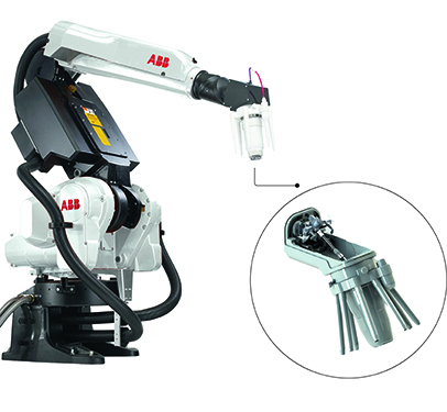
For industrial robotics, eg, paint robots →1, lightweight structures would positively impact robot cycle time, accuracy, payload and energy consumption by reducing time and cost. In particular, the paint atomizer module located at the end of a paint robot arm would benefit from weight reduction →1. Furthermore, AM techniques might yield additional advantages: ease of assembly, easier cleaning and improved component robustness.
The function of the paint manifold is to mix two components of a paint (resin and catalyst) right before atomization →1. Traditionally manufactured from a stainless-steel block using conventional CNC machining, the inner side of the manifold consists of a complex of network pipes – making the production of the manifold costly, increasing material waste and delivery time. Consequently, roughly 88 percent of the initial stainless steel block is machined away.
Any addition of unnecessary material to an AM component will increase the weight and add to the cost of the final part, so printing lightweight structures is crucial. Weight optimization is accomplished usually through topology optimization (TO). Initially, service loads are applied to the component. The optimization engine derives the density of each element that is required to maintain the structural stiffness of the component. The resulting density map of the component can then be used to produce a typical bionic structure or a lightweight lattice structure.
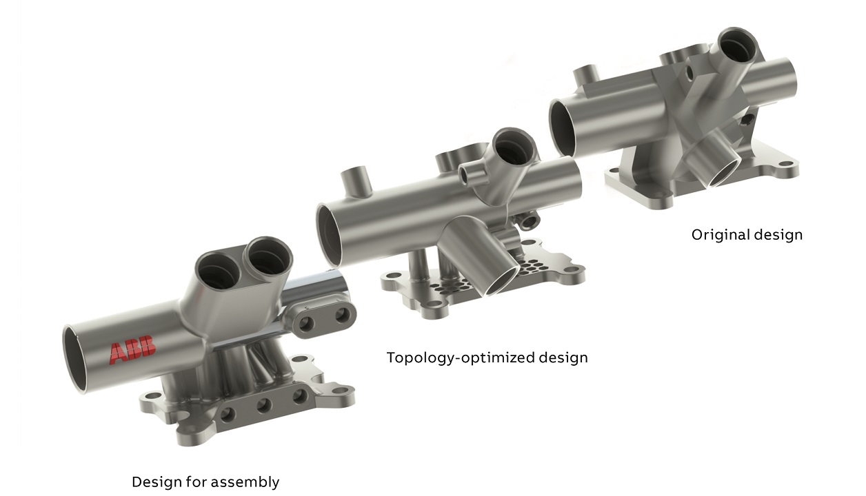
ABB successfully demonstrated that AM is especially well-suited to manufacture these types of complex shapes. The lightest version of the manifold exhibits both bionic and honeycomb features →2. Total weight was reduced by a phenomenal 43 percent while functionality and structural stiffness were preserved.
Next, the manifold was redesigned to improve the printing process and ease the post-CNC machining step. A dedicated computer software was employed to optimize the orientation of the component during the printing process. Volume of support (eg, waste material), printing time, deformation, amount and ease of post-processing and number of parts that fit on a building plate were all evaluated with the aim of improving part quality and cost. Printing time was reduced by 10 percent while the volume of support required was reduced by an extraordinary factor of six.
Later, the design of the manifold was modified to ease the assembly →2. In contrast to traditional manufacturing techniques, which can limit the shape of inner channels to straight holes, AM offers the possibility to produce curved channels that extend freely inside the structure. The path of the air channels could then be redrawn freely inside the manifold so that all of the air pilot valves could be placed on the same side of the component →3. The result is ease of assembly and a more rational post-CNC machining.
ABB employed the SLM technique to produce prototypes of this new generation of manifold; this resulted in a significant weight reduction, ease of assembly and reduced the amount of material waste. Component delivery time was shortened from three months to only three weeks.
Altogether, this improved manifold provides ABB’s customers with a better design and makes enhanced robot performance highly accessible.
Topology optimization of a robot arm
The main advantages of AM technology (design freedom, easy manufacturing of complex parts, printing-on-demand) are impaired during the 3D printing of robot components (eg, aluminum arms in which there are limited number of materials available, small size of components, high production cost and long printing time). In contrast, classical methods, eg, casting, are highly efficient and applicable to a virtually unlimited size range of components. For this reason, ABB evaluated a hybrid strategy of production. First, the lower arm of an industrial robot was optimized topologically [3,4], in order to discern various design alternatives →4a,4b.

03a Comparison of the inner channels - original design 
03b Comparison of the inner channels - the design for assembly components.
Thereafter, the sand mold was produced by 3D printing and then treated as a tool in the subsequent manufacturing process: classical casting. ABB developed a completely new concept of the robot’s lower arm, one that pushes beyond the previous limitations of AM technology.

04a The results of various design concepts is shown. 
04b Simulation of the mold filling process. 
04c The resultant cast demonstrator of a lower arm of an industrial robot.
04 Various design concepts were proposed by optimization algorithms.
The demonstrator →4c resulted from a unique mixture of three different technologies: the generative design, which helps engineers to propose concepts of free-form shapes; the additive manufacturing, which produces the pattern (the tool) instead of the part itself; and metal casting, which materializes the designer’s idea using a 3D-printed mold and the strong yet lightweight metal alloy.
In this way, ABB demonstrated that it can be more profitable to produce a tool using AM technology, and then employ this tool to advantage during standard manufacturing processes.
AM-based tooling for injection molding
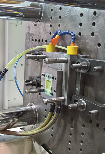
AM technology has resulted in higher resolution 3D printers that are faster and more accurate than ever before, and in the development of new materials for use in the injection processes. Consequently, several AM vendors proposed the direct 3D printing of injection mold cavities [5,6], without the need of subsequent cavity machining ie, ready to be adopted on a metal mold frame →5.
The 3D-printed polymeric injection cavities are priced lower than metal tooling (usually 50 to 70 percent less) with a much shorter lead time (days). Unfortunately, 3D-printed polymeric molds are best suited for jobs up to 100 shots (depending on the material type and mold complexity) due to current technological limitations. Other constraints include: the range of thermoplastics that can be processed, high cost of raw material for 3D printing and long injection molding cycle time (15 to 20 times longer than for metal cavities) due to the low thermal conductivity of polymers used for 3D printing. ABB proposed a completely new approach to overcome these aforementioned limitations. 3D printing is used to produce a shell structure only, which is then filled with material of a higher thermal conductivity. The thickness of the 3D-printed shell structure is the fundamental consideration during the design stage when the contradiction of requirements must be considered: a small thickness is associated with a short cycle time whereas a large thickness ensures good mechanical stability. The impact of the shell thickness on cycle time (cooling efficiency) was assessed using Ansys/Fluent on the geometry →6.
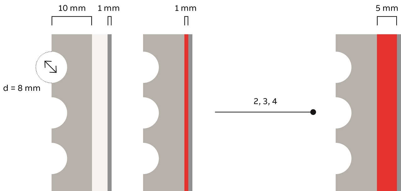
The thickness of the shell wall (from 1 mm to 5 mm) and the solid structure (polymer and steel) were studied. Selected computational results of cavity surface temperatures for analyzed scenarios during the first and stable cycles →7 show the extreme impact of shell thickness on cooling efficiency, even during the first cycle.
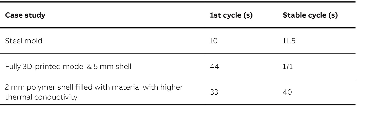
The cycle time following attainment of stable processing conditions, for solid polymer cavities is circa 15 times longer than for steel cavities. This essential final consideration and optimized design allows the cooling time to be reduced by a factor of four to seven; this translates to a cycle time that is only two to three times longer than for steel molds – an excellent result.
Outlook
AM and all its technological benefits are changing the way products can be designed and produced. AM is already mature enough to compete with traditional subtractive manufacturing processes or production technologies like injection molding in terms of material properties, dimensions of geometries, material and process costs. Companies developing simulation software, AM machines and materials providers are expected to continue their efforts to offer customers ever more user-friendly and automated solutions. Customers will benefit from greater freedom and flexibility in terms of geometry; this results in lightweight structures and excellent mechanical performance in functional integration and in parts consolidation.
Currently, ABB is investigating another trend, namely multi-physical numerical simulations of the printing process itself; this includes thermo-mechanical interactions between single particles and layers of the printed object (of metallic and polymeric powders). ABB will present these simulation results once the tests and intensive verification procedures are completed.
References
[1] Wohlers Report 2016, “3D Printing and Additive Manufacturing State of the Industry,” Wohlers Associates Inc. USA, 2016.
[2] B. Stucker, “Physics-Based Simulation: Accelerating Innovation in Additive Manufacturing.” 12th Intl. Conf. Additive Manufacturing and 3D Printing, Nottingham, UK, 2017.
[3] Y. Saadlaoui, J. Milan, J. Rossi, P. Chabrand, “Topology optimization and additive manufacturing: Comparison of conception methods using industrial codes.” J. Manufacturing Syst, vol. 43, Part 1, April 2017, pp. 178–186.
[4] M.K. Thompson, G. Moroni et.al., “Design for Additive Manufacturing: Trends, opportunities, considerations, and constraints.” Manufacturing Tech., vol. 65, Issue 2, 2016, pp. 737–760.
[5] R.A. Harris, H.A. Newlyn and P.M. Dickens, “Selection of mould design variables in direct stereolithography injection mould tooling.” Proc. Instit. Mech. Eng., Part B, J. Eng. Manufacture, vol 216 No. B4, 2002, pp. 499–505.
[6] G.V. Salmoria, F.V. Lafratta, M.M. Biava and P.Z. Ferreira, “Rapid manufacturing and rapid tooling of polymer miniaturized parts using Stereolithography”.
J. Brazilian Soc. Mech. Sci. and Eng., vol. 30, No. 1, 2008, pp. 7–10.