Power grid equipment should be compact and efficient – but should also handle extreme thermal stress. Digital design methods are indispensable in achieving this aim. Recent breakthroughs in electrothermal simulation have made the technique a valuable tool for the power equipment designer.
Jörg Ostrowski, Andreas Blaszczyk ABB Corporate Research Baden-Dättwil, Switzerland, joerg.ostrowski@ch.abb.com, andreas.blaszczyk@ch.abb.com; Boguslaw Samul, Remigiusz Nowak ABB Corporate Research Krakow, Poland, boguslaw.samul@pl.abb.com, remigiusz.nowak@pl.abb.com; Michael Gatzsche ABB, High Voltage Products Zurich, Switzerland, michael.gatzsche@ch.abb.com; Valeri L. Oganezov ABB Electrification Products, Saint-Laurent, Quebec, Canada, valeri.l.oganezov@ca.abb.com
Pressure to be compact and efficient, and the demanding and varied power landscape in which it operates, makes thermal stress a critical design consideration for modern grid equipment. In order to predict thermal stress in a power device or system, it might seem sufficient to calculate electromagnetic behavior and heat transfers.
However, for a successful, comprehensive calculation, many physical effects must be considered and simulated – a task that overwhelms traditional heuristic design approaches. A digital design approach must be taken.
New tools for simulation and co-simulation
Whereas resistive and inductive losses, and heat conduction, have been computable for some years, the important losses at electrical contacts or the mixed convective-turbulent-radiative heat transfer mechanisms at the surfaces of realistic devices became predictable in a precise way only recently thanks to Maxwell-CFD (computational fluid dynamics) co-simulation. Sophisticated mapping algorithms, automatic mesh refinement and error control are important numerical companions of such simulations. These new tools mean that thermal stress in power devices can now be predicted with high precision and comparatively low effort.
The integration of large parts of such simulations into a CAD system, as was accomplished for the ABB Simulation Toolbox in recent years, now allows the relatively simple execution of complex simulations. Parametrized CAD-integrated simulation models allow the quick and accurate analysis of a multitude of possible product variants under different loads. ABB was a pioneer of these CAD-based simulation twins, which will be employed for engineering in the digital factory of the future [1].
In particular, ABB pioneered advanced, comprehensive methods for electrothermal calculations, which are critical for the successful design of modern power equipment. A number of such methods are already in use by ABB’s product designers. The choice of method depends on the simulation task and three examples serve to give a flavor of the power and flexibility of the approach.
Maxwell-CFD co-simulation of a medium-voltage outdoor breaker
One of the most accurate and detailed methods for computing electrothermal processes is based on two-way-coupled Maxwell-CFD co-simulation. Here, the electromagnetic power losses are calculated by a finite element solver of Maxwell’s equations and the heat transfer is computed by a CFD solver. The two solvers exchange information during the calculation in such a way that all electrothermally relevant effects can be considered.
The usage of the two different meshes for the two different physical domains enables a resolution of local phenomena that might otherwise be impossible. In the case of convective cooling, examples of these phenomena are skin effects that concentrate the power losses close to the surface of the conductors and thin turbulent boundary layers at the outer surface of the solids that are decisive for the heat transfer to the environment.
ABB researchers developed effective computational tools to conduct such a highly complex simulation. A 3D electrothermal analysis of an arc-resistant outdoor medium-voltage (MV) circuit breaker can be used as an example →1.

01a Outer view. 
01b Inner components. 
01c Simplified model for thermal subanalysis.
01 MV outdoor arc-resistant circuit breaker.
Circuit breakers are one of the most important components of MV power distribution networks as they ensure proper load switching and protect downstream loads and upstream networks, including major items such as power transformers.
The thermal behavior of the circuit breaker is a vital factor in its operation. Overheating during normal operation may shorten its life and damage main components. Overtemperatures caused by overloads may damage the breaker insulation and lead to electrical breakdown.
One challenge was that forced cooling is not allowed during breaker overload but, nonetheless, the unit is expected to reliably operate between -50 and +40 0C (the unit is designed for up to 60 percent overload at extremely low temperatures, for instance). The thermally insulated enclosure - designed to IP43 - has well-protected ventilation grids, which limit air circulation and thus reduce the effectiveness of convection cooling. This aspect further complicates the design process and may lead to multiple design iterations and retests.
Devices such as circuit breakers have their thermal behavior verified during temperature rise tests that require controlled environmental conditions, a physical model of the device, a suitable power supply and a test infrastructure (thermocouples, etc.) A test may take many hours to reach a stable temperature. Of course, such a test procedure is indispensible for the final type testing of a device, but it is an expensive way to test early design variants, some of which may be discarded anyway.
In contrast, computerized virtual temperature-rise tests enable very fast and relatively inexpensive validation of different breaker designs under a variety of loads and environmental conditions.
The simulation model of the MV circuit breaker in →1 includes electromagnetic and thermal (CFD) submodels that exchange data. In the electromagnetic model, even if the device has geometrical symmetry, current paths of all three phases are considered, on a account of the asymmetrical current loads and proximity effects. Thermal-flow simulation was performed for only half of the device, thanks to its geometrical planar symmetry.
The complete simulation process included all physical effects that occur during the standardized heat test. In the case of electrical losses, and skin and proximity effects, the influence of temperature on material resistivity as well as electrical contact resistances were considered. For thermal calculations, turbulence effects in buoyancy-driven flow together with thermal radiation were taken into account. Other details, such as the influence of ventilation grids on air exchange between the breaker interior and ambient environment, were also included.
Coupled simulation is an iterative process and data was exchanged between the two solvers until a stable temperature (±5 percent) was reached, which took four iterations. With a maximum deviation of 5 K, simulation results matched actual temperature rise test results almost perfectly →3,4. This example illustrates how simulation can deliver reliable results and reduce the number of real test iterations.

03 Final temperature distribution inside an MV outdoor circuit breaker. 
04 Simulation accuracy – comparison with physical measurements.
Network model of a dry transformer
It is not always possible to use the computationally expensive Maxwell-CFD co-simulation, especially for large complex
devices or if one is aiming for automated design optimization. In such cases, simplified analytical descriptions are used, eg, thermal equivalents to electrical circuits – the thermal networks. Such networks are not necessarily precise but are computationally much more efficient.
Traditionally, the thermal network approach has been used to evaluate the temperature rise of transformer coils [1] →2.
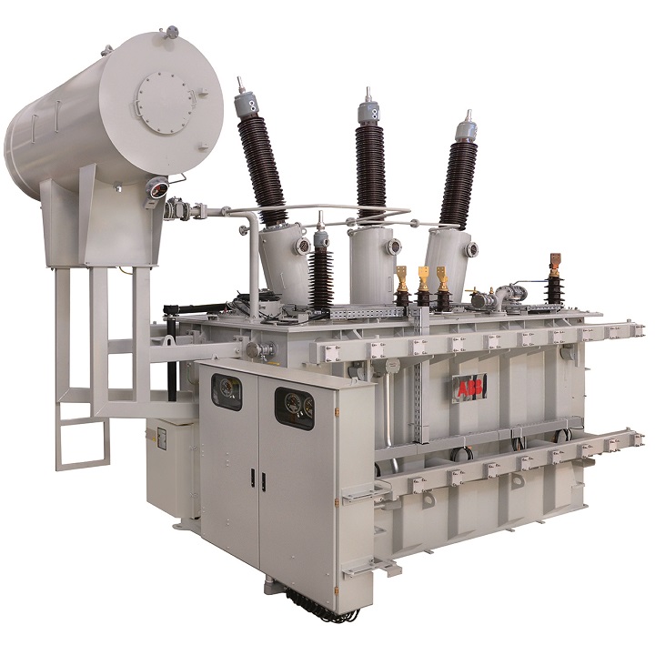
Recently, developers of the ABB transformer design tool extended the network model and enabled computations of the whole cooling system [3] →5.
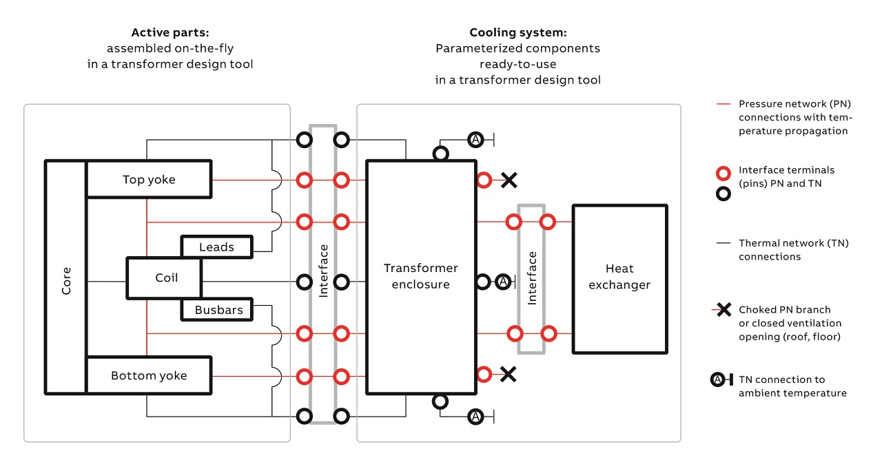
The active parts that generate heat are connected with the cooling system via a predefined interface that allows the transfer of fluid and heat between components. The cooling system includes an enclosure as well as an external heat exchanger with another interface between them. The interfaces make it possible to combine all implemented network components and define an arbitrary configuration according to designer specifications. Standalone transformer operation (without enclosure) and open ventilation (as a replacement for the heat exchanger) are included as available options.
As an example of component implementation, a pressure network model of a dry transformer enclosure is shown in →6,7.
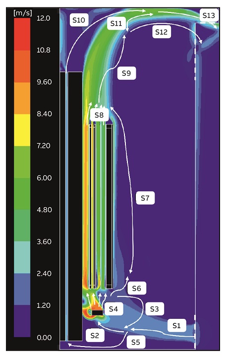
The streams of air identified in a CFD computation have been used to create the network topology. The CFD result has been used to validate the accuracy of the network model within the required parameter range. Typical parameters are: dimensions of the enclosure, internal fan data and flow resistance of ventilation grids. The network model can reproduce the circular flows inside the enclosure.
![07 Pressure network with airflow branches (black arrows) corresponding to CFD results from →6. Temperature propagation wires, as well as the thermal network, are not shown (only the coupling PN/TN is) [3].](https://resources.news.e.abb.com/images/2019/5/28/0/electrothermal_simulations_design_m8072-07-EN.jpg)
The full model can compute coil temperature rise, taking into account all details of winding, core and the cooling system, within seconds This approach allows designers to keep within the required temperature limits and minimize material costs.
Simulation of short-time current test of an earthing switch
Mandatory short-time current (STC) tests drive a high current of short duration (some seconds) through a device to mimic a short-circuit and thus test the device’s withstand capability. As STC tests are elaborate and costly, STC simulations that reliably predict the temperature rise in the device are valued.
A Maxwell-CFD co-simulation approach here would be overkill as the heat flux from the device to its environment is low. In fact, the entire CFD part can be represented as simple transient heat conduction in solid parts of the device. Of much higher importance for STC tests is electromagnetic modeling. The major effects that need to be considered here are:
• Ohmic losses in the volume of the device.
• Temperature dependence of the electrical resistivity.
• Ohmic losses due to electric contact resistances (ECRs) at conductor interfaces.
The latter effect is the most complicated and cannot be neglected because these losses may amount to up to 50 percent of the overall losses. In addition, in switches, the losses occur locally at the surfaces of the electrical contacts and are not distributed throughout the entire volume (as is the case for ohmic losses within the material).
Consequently, the hottest and most vulnerable areas are in the neighborhood of the electrical contacts. Modelling of ECRs is a multiphysics topic extensively studied worldwide.
In the simulation of a gas-insulated switchgear (GIS) earthing switch, a constant – ie, temperature-independent – contact resistance was assumed [4]. This is the simplest representation of a contact for which the increasing electrical (material) resistivity during heat-up is compensated for by a decrease of the contact resistance due to a larger contact area caused by material softening.
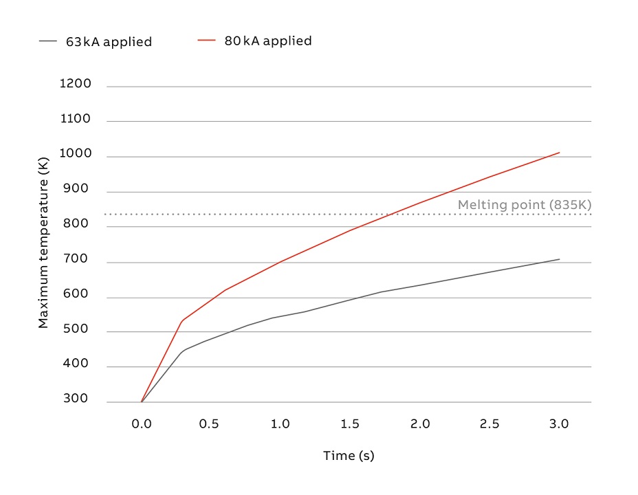
Two STC tests – in which RMS currents of 63 kA and 80 kA, respectively, were driven through the earthing switch for 3 s – were simulated and also carried out in the laboratory →8,9.
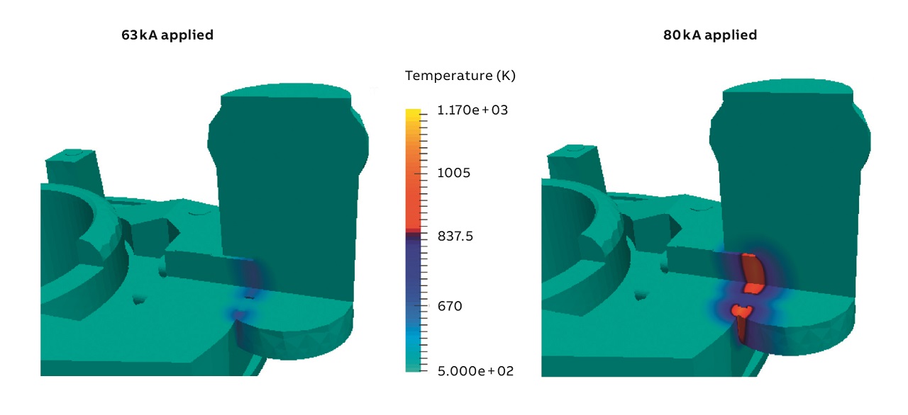
The real-life prototype passed the 63 kA test but failed after approximately 2 s in the 80 kA test, closely reflecting the simulation results. A new 80 kA design was developed.
Modeling the future
As electrothermal simulation tools improve further and co-simulation becomes easier and more powerful, better model resolutions will be possible and models will reproduce the real-life device experience even more closely. Power equipment is going through a period of great change due to trends such as digitalization, distributed generation, inter-regional power transfer and the effects of highly variable renewables. The more powerful and more sophisticated simulation and co-simulation tools under development will find good use.
References
[1] A. Blaszczyk et al., “Simulation Toolbox – Dielectric and thermal design of power devices,” ABB Review 3/2013, pp. 16–21.
[2] R. Nowak et al., “A 3D electro-thermal simulation of the outdoor medium voltage circuit breaker,” IEEE Transactions on Power Delivery (in review process).
[3] A. Cremasco et al., “Network modelling on dry-type transformer cooling systems,” COMPEL – The international journal for computation and mathematics in electrical and electronic engineering, Vol. 37, Issue 3, 2018.
[4] J. Ostrowski et al., “Simulation of short time current tests of industrial devices.” Accepted by SCEE 2018, Springer Series “Mathematics in Industry.”