Jarosław Nowak, Equipment Analytics, ABB Marine & Ports
Morten Stakkeland, Data Scientist, ABB Marine & Ports
Digital transformation in the marine industry is creating a new collaborative mentality, where shared data and integrated systems can work to meet common challenges. ABB is leading the way in with a data driven, iterative approach to building digital twins as a key element of the cloud infrastructure, integrating edge-based analytics from equipment at sea and vessel models to achieve continuous improvement in both product development and life cycle management.
Introduction
There have been many attempts to describe and define the concept of digital twins, but it is fair to say that disagreements remain as to the term’s meaning. In all humility, the authors of this paper will avoid theoretical discussions and exercise restraint over futuristic visions on what digital twins can become. Instead, we will focus on the benefits available outlining how digital twins can be implemented and used to provide digital services that add value to marine systems. The paper will also demonstrate how the digital twins are integrated into systems on board and on shore, and describe the infrastructure that facilitates their development, deployment and updating.
Two use cases will be offered, where digital twins are used: for benchmarking and measuring performance in a DC-grid electric propulsion system; and for condition monitoring of rotating machinery;. The use cases will illustrate practical themes that can be overlooked when digital twins are discussed. An electrical propulsion motor is a component in all the two use cases, but the corresponding motor models share few if any common structures. The digital twin must be adapted to the application, rather than encompassing all possible information. First, therefore, the cases will demonstrate how different applications require different models, structure and inputs. Second, they will illustrate a key supplementary point of this paper – that the development, application and maintenance of digital twins is an iterative process. One example will demonstrate how several iterations and onboard changes were needed to improve data quality to a sufficient level for the model to be considered accurate enough. In a second example, the digital twin was applied to modify and improve the onboard system.
Digitaltwins
The treatment of digital twins in this paper will lean heavily on the systematic treatment, concepts and classification provided by Cabos and Rostock (2018). They propose the following four business drivers for investing in digital twins:
- To increase manufacturing flexibility and competitiveness
- To improve product design performance
- To forecast the health and performance of products over lifetime
- To improve efficiency and quality in manufacturing
This article will focus mainly on the second and third points, as it relates principally to the way the application of digital twins are integrated into the ABB Marine & Ports business unit. Within its portfolio of digital products, ABB Marine & Ports offers systems and services that support our customers in various aspects of vessel and machinery operations (Figure 1).

Following Cabos and Rostock (2018), the three constituents of the digital twin are:
- “A. Asset representation: i.e. a digital representation of a unique physical object (e.g. a ship or an engine or part of it)” - see section 3.1, ‘Asset model versus system model’ covering to some extent, the semantics of collected data
- “B. Behavioral model: Encoded logic allows predictions and/or decisions on the physical twin”; this will be discussed in chapters related to data collection and use-cases where some examples are given of modeling methods developed in knowledge-based approaches, through system functions and ending with purely data driven machine learning models
- “C. Condition or configuration data: Data reflects the status of and changes to the unique physical object during its lifecycle phases”; this is, in fact, a description of the digital twin enabler e.g. the computerized system of systems thoroughly described in chapter 3, ‘Infrastructure for implementation of digital twins’.
Infrastructure for the implementation of digital twins
To secure all of the benefits available from the digital twin, digital infrastructure needs to be established both on board the marine vessel and at the onshore infrastructure where data is received (later referred to in this paper as the cloud). There are certainly different ways of implementing such an infrastructure and different terms associated with its description: we will use a term ‘system of systems’, which in principle is a collection of task-oriented or dedicated systems that pool their resources and capabilities to create a new, more complex system offering more functionality than the sum of its parts. The systems described in this paper can be listed in the following way:
- The diagnostic system i.e. the data collection and analytics system deployed on board as well as in the virtual environment/cloud (here known as the ABB Ability™ Remote Diagnostic System).
- The decentralized control system, having multiple layers, out of which control/field network and client network are to be discussed.
- The remote access platform software solution that implements secure remote connections and processes data transfer.
- The Microsoft Azure cloud infrastructure enabling the deployment of the virtual environment to host the on shore digital twin and facilitate storage of both raw and recalculated data in a simple and readable format of SQL tables or flat files.
- The dashboarding application for data visualization and sharing part of entire on shore digital twin with various data consumers, e.g. ship operators, vessel management companies, and other vendors.
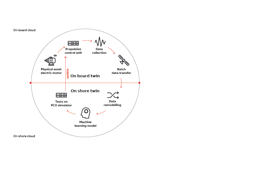
The building blocks of the digital twin infrastructure and the entire cycle of data transformation and its processing to build and iteratively update behavioral aspects of the digital twin is presented in Figure 2. Each aspect of this environment is tagged with either A, B, or C (as listed above). This provides context and relates practical implementation of certain blocks to the concept of the digital twin.
In principle, what is presented in Figure 2 is a system of systems capable of collecting data on board according to different sampling regimes, performing analytics on site for decision support and data size reduction, compressing the data before securely transferring it to the cloud data centers and finally processing data (from single assets/systems or from the fleet) to build and iteratively update digital models of the physical assets on board.

Later, most of the blocks and aspects presented in Figure 2 will be discussed in detail but it is worth highlighting:
- Asset representation, i.e. conceptual modeling of assets and asset systems on board and in the cloud with their practical implementation when used with structured XML documents. Here we address which data we are going to collect.
- Data collection, i.e. securing insights on how interfacing with other digital systems and smart devices on board implement the digital twin and what are the main choices for communication protocols. Here we address how we collect data, giving high priority to reusing existing digital infrastructure rather than replicating data sources by adding more sensors and physical connections. The aim is to minimize the investment cost of building the digital twin, yet not to lose information that is critical to building proper digital model.
- Edge analytics, i.e. analytics performed on board the vessel as the essence of the behavioral aspect of digital twins. Here we would like to explain the process of manipulating data in order to predict the condition of the actual physical asset.
- Data transfer from on board to the cloud infrastructure involves data selection, compression, secure transfer and remodeling on consumer side. Until this point, we have concerned ourselves with the infrastructure for the onboard twin; now, we also need to consider the on-shore twin.
- Cyber security is also considered in all steps presented in Fig.2, and therefore merits a separate chapter beneath.
- Once data leaves the vessel, they are processed further on the cloud side. This process often requires remodeling the structure and meta data information so that fleet-level analytics can be applied. Having data in the cloud also opens opportunities for collaborative work involving human experts from different disciplines to improve models and analytics without necessarily connecting to the infrastructure on board. Improved models and recommendations can then be applied to the on board digital twin to maintain consistency between the digital representation of the physical asset on board and on shore.
Asset vs system representation
There are different ways of structuring information and the data that describe digital representations of physical assets. One way of modelling a physical asset is to provide static information that will not change over its lifetime. These types of information are called ASSET INFOS and might include the bearing type, serial number, rating plate information such as the nominal speed of the motor or the nominal power. Another type of information that is more dynamic concerns actual measurements - otherwise known as INPUTS. Example of inputs are measured speed, temperature or current. INPUTS are representative measurements taken from source (such as sensor or other digital system) without any pre-processing. Interesting factors in the definition of the INPUT include its type (numerical or textual, time series or equispaced vector), its origin (e.g. information about data source location) and the sampling rate in the case of simple data readers. The third type of information covers RESULTS, which is the digital information on how the INPUTS and ASSET INFOS have been processed according to the behavioral aspects of the digital twin model. RESULTS can also be numerical values (for instance root mean square values calculated from raw vibration data) or textual (such as warning information that the condition of the physical asset is starting to deteriorate).
An important note at this point is that although we typically have some predefined structure for ASSET INFOS, INPUTS and RESULTS that describe the physical asset (i.e., we have an equipment model in place), these definitions can and will change over the course of the iterative process of updating models and digital twins. Therefore, it is important that our infrastructure can accept multiple changes in the definition of, for example, INPUTS where the sampling rate of the signal changes or RESULTS where the underlying assumptions we use in equations and analytics are altered, e.g. by economic impacts.
One language (or to be precise, one markup language) that can be used to describe the physical asset in the digital world is XML – extensible markup language – which is widely used in IT, mainly in SOA (Service Oriented Architecture) applications. XML also finds an application in describing the configuration of the digital twin discussed here, mainly because it combines flexibility with clear syntax. In addition, although XML does not use standardized semantics, conventions in XML naming mean it is practically self-explanatory for any domain expert wanting to understand the difference between motor speed and hull number.
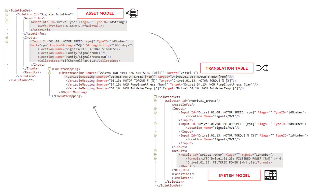
Another aspect of modeling physical assets that needs considering is the structure of the meta model. In principle, meta models should describe relations between digital data collected to build the digital twin so that it reflects the function of the modelled assets or its place in the wider hierarchy. In this case, we are using the term asset model as a definition of a single physical, repetitive object, as opposed to a system model where strict criteria for encapsulating the meta model are released. For example, instead of building the meta model for an electric motor, we are more interested in the meta model of all of the energy producers and consumers that are playing a role in the behavioral model of the vessel’s energy efficiency calculation. In case of asset type modelling, it is crucial that the model can be standardized and deployed multiple times without additional re-configuration (or engineering). An example of such an object modelled as an asset would be an electric motor, or pump or propulsion control system. In all of these cases we can define a standard set of XML elements and attributes and treat them as a template for the digital representation of the motor, pump or specific local control system. As a consequence, the names of properties and attributes will be the same for all instances of assets modelled this way. It is still possible to position such an asset in the broader hierarchy of subsystem or system so that its individual associations or location are treated as unique asset identifiers.
There are many reasons why templates and predefined asset models are applied but the main drivers will obviously be economic. It is much quicker, easier and cheaper to engineer and deploy digital infrastructure of complete vessel propulsion machinery if we simply install multiple standardized asset models. One example could be deployment of an electric propulsion system that consists of digital representations of 2 frequency converters, 2 electric motors, 2 transformers and 2 propulsion control systems, where each of them is deployed as an equipment type template. Another example could involve sensor fusion techniques for system level fault detection: here we could identify the effect as it appears within the asset (for instance high temperature of motor winding) and correlate that with the real cause that may have originated elsewhere in the hierarchy (for instance, it may be due to suboptimal performance of the motor’s control loop). In this case, we should translate the asset model properties to system model properties. In the era of big data, cheap cloud storage and systems that easily scale up for different calculations needs, such an approach is far more reasonable than was the case even 10 years ago.
Figure 3 shows a very simple example of an asset model-type xml template used to describe different properties of a frequency converter which can be translated into another system. Highlighted with the red boxes are examples of ASSET INFO or INPUT with various properties describing how actual values are going to be acquired (data source address and sampling rate) and where they are going to be stored (database, flat files, volatile memory). In the system model example that follows the same XML syntax, there is an example of the RESULT element with the attribute
360
14
One final note on the modelling of physical assets in digital application is that this process is expected to be done in iterative way. However, this depends on the business model: there may still be cases where the system - once delivered – is never to be changed. In the era of digital transformation and digital twins, however, we are seeing growing opportunities (and demands) to add different types of services, decision support systems, intelligence and analytics. All additional inquiries can be addressed using iterative updates of asset and system models as well as translation tables.
Data collection
Once the static definition of physical assets has been established in XML and deployed within the diagnostic system runtime/multi-tier software architecture paradigms (data storage/management, application processing and business intelligence are separated by process and node), it is time to deploy scenarios for a dynamics of digital twin. For example, we need to know from where and how often measurements will need to be acquired to trigger relevant calculations. This topic is very wide-ranging in itself, so we will limit ourselves to a few selected observations.
Communication interfaces
Nowadays, most marine applications are already digitalized to some extent. Typically, there are VMS (Vessel Management Systems) in place that allow operators to supervise and control most critical operations and processes. With this in mind, we may already expect that there will be some computerized infrastructure in place - sensors, controllers, operating stations etc., all connected via field networks or Ethernet into the control and automation system. These systems exchange information over communication buses using various protocol types: from the closed, proprietary ones that are typically vendor-specific, to open ones that support agreed international standards. Our discussion will focus on the OPC standard (OLE for process control) protocol, which is well established and is a widely used way of exchanging data for non-critical and non-real time applications. Recent development by the OPC Foundation group has created new specifications, such as OPC UA (Unified Architecture), that provide more platform independence, openness, security and service-oriented architecture. Although the OPC UA standard undoubtedly offers a good way of closing the gap between traditional industries and modern trends in IT, it should be noted that it does not often appear in marine applications.
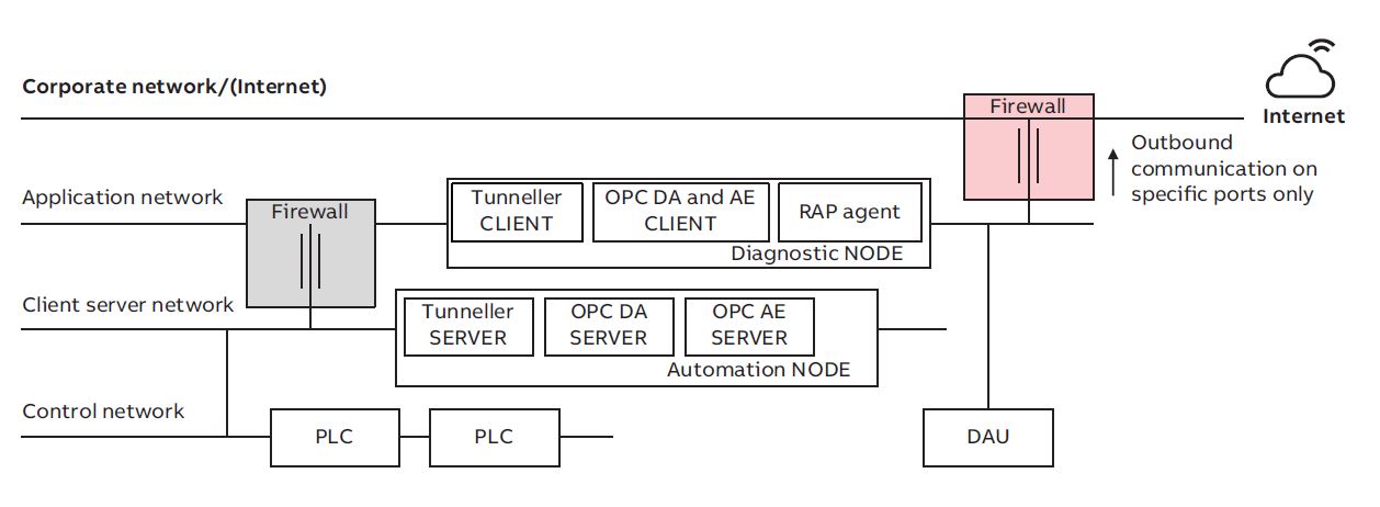
Figure 4 presents an example of network topology that can be found on board the types of vessel included in the case studies explored beneath. From the perspective of data collection, it is important to highlight that the data provider node (in this case OPC Server node in the Client Server network) is physically separated from the OPC CLIENT that receives the application (in this case, the on board digital twin). Depending on the OPC CLIENT requirements for the signals and refresh rates, the OPC Server creates corresponding signal groups and the CLIENT subscribes to that and is notified about each change of the signal value.
Smart data acquisition
The most basic mode for digital twin data exchange to take place between the OPC CLIENT and OPC SERVER is by time-scheduled request to acquire data from the server for delivery to the client side. For the sake of simplicity, we can call this functionality a reader. In an ideal world, the OPC CLIENT would ask that OPC SERVER for data as frequently as required. In practice, there are limitations: the more data stored, the higher the storage costs; there are network bandwidth limitations; there are also OPC tunneller limitations and OPC server implementation limitations, meaning it simply may not be possible for the OPC SERVER to provide data as frequently as the OPC CLIENT requests. There are, however, ways to bypass some of these limitations without losing information.
The first approach is to use both synchronous and asynchronous interfaces for OPC CLIENT-SERVER communication. Using an asynchronous interface, the OPC Client does not interrogate the server at every requested interval. Instead the server notifies the client when data has exceeded the user-specified deadband; at that moment client is prompted to seek data. The advantage of such an approach is that quite a short interval can be set but data should only be transferred when there is a change. This minimizes traffic between server and client and saves on storage. If a ship is at rest in the harbor, for example, the reference speed for the propulsion motor is zero, meaning that there are no values to be ‘pulled’ and recorded on the client side, even though data may be being requested on a second by second basis. The drawback is that, if the ship stays in the harbor for couple of days, our digital twin will have a data gap and the data consumer may not be sure if this is due to failure of the recording system or to asynchronous reading. In order to solve it one can add additional reader that uses synchronous interface with longer intervals (e.g. minutes, hours). With synchronous read, OPC client always polls the OPC server at regular predefined intervals and server is supposed to call back and provide the data.
Another approach for reading data in a smart way is to create logical scenarios where the OPC client monitors specific variables and responds when they exceed predefined thresholds to prompt a separate batch of OPC Client Server calls to collect data at a high sampling rate for a predefined period. After that, the data pull is suspended. Yet another approach involves receiving the data, but engineering and compressing it in a way that it is cost-effective to store and quickly accessible for specific analytics.
In the marine context, the rate of sampling should in general be adapted to the dynamics of the sampled process or signal, in order to measure, analyze and model the underlying functions. For instance, it may be sufficient to sample the propulsive power once every minute for a large tanker with conventional propulsion but sampling every few seconds may be necessary to monitor the performance of DP system components. Clearly, frequency of collection is determined by usefulness, but data volumes and connectivity are also considerations, especially given the volume of data available for collection on board a complex modern vessel.
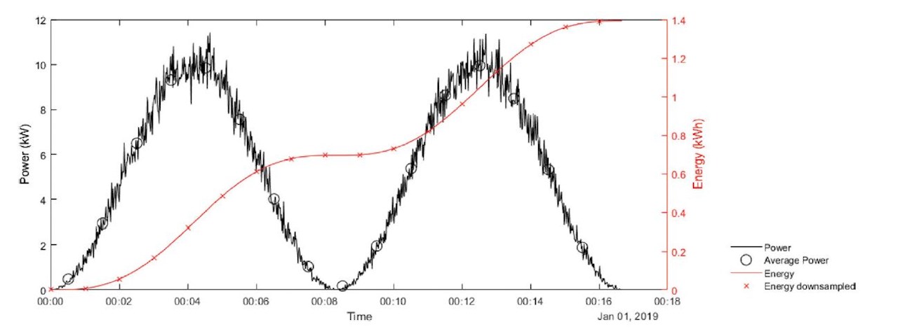
Integration and downsampling of signals are useful techniques that in some cases can be applied to reduce the size of the data stream. For instance, consider an auxiliary pump in some subsystem on a vessel. In this particular case, the data engineer considers two variables to be of interest; the energy consumption and the accumulated running hours. When calculating the energy consumption, the first step would be to integrate the measured power in order to calculate the accumulated energy in units of kWh. When integrating, the sampling rate should be high in order to optimize accuracy. Accumulated energy consumption can then be downsampled without any loss of accuracy, the only loss being temporal resolution. Here, the main idea is to calculate the integrated signal using edge analytics and transmit the downsampled signals to shore. The average power consumption can easily be calculated from this integrated signal. The example is illustrated in Figure 5, where power is measured every second, then integrated and downsampled once every minute. The average power is therefore calculated every minute. Note that for the sake of robustness, the integration should be performed as close to the signal source as possible, preferably on an industrial grade, redundant device. The integrated signal then also has the advantage of providing useful information during periods where communication between the data collecting edge device and the device itself is lost due to maintenance, network issues or other problems. The accumulated running hours should be calculated in a similar manner. The number of hours the pump is running should be accumulated at the edge device, and downsampled at an appropriate rate. One sample per day may be sufficient in this case.
Edge analytics
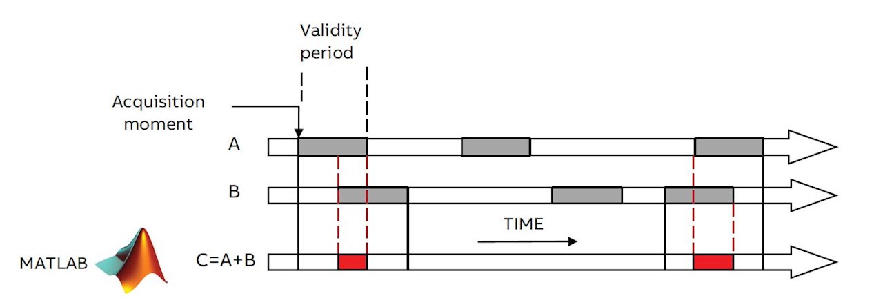
Once data are collected, transformed or downsampled, they can be processed by certain analytics already on board the vessel to derive meaningful KPI (Key Performance Indicators) for decision support. This type of analytics is called edge analytics as they happen within on-site systems. The diagnostic system that is a main enabler within the digital twin infrastructure can calculate results automatically when data arrives that are defined as inputs for those results. In case studies described below, discussion typically focuses on time sequenced data, where time stamps act as the reference points for the calculation engine to pick up the right values and use them to calculate final result (see Figure 6).
The pair Stamp ‘ValidFor’ is used in performing time-sequenced computations. Here, values can only be combined in computation when their validity periods overlap. Figure 6 illustrates how this might happen for a sample expression A+B. Note that when periods do not overlap, there is no result produced, ABB Marine & Ports (2017).
In practical applications, formula A+B is typically the result of quite complicated signal processing analytics that, for instance, calculate the FFT algorithmic spectrum out of collected vibration data. The body of these FFT calculation analytics may require tailormade signal processing functions or a call to an existing library embedded within calculations runtimes such as MATLAB or R.
Often, some results become inputs for other results, and hundreds of results may derive from a relatively small number of initial inputs that represent sensor measurements. The entire batch of equations may require regular updates and modification as we learn more about the behavior of the physical asset and introduce changes and improvements in the chain from data collection scenarios to edge analytics. The point here is that every update of the formula for C e.g. from C=A+B to C=2*A+B triggers automatic recalculation of the underlying results so that the digital twin updates itself automatically. For real-time or close to real time applications, where criticality of edge analytics is high, one must consider transferring calculations to the control layer and deploying them on board programable controllers. An example of such an approach is described below in the use case for motor temperature protection.
Cybersecurity
From marine market observations over last 5-8 years, there has been a significant increase in cybersecurity awareness. Traditional vendors of digitalized systems, especially global companies such as ABB have long had the cybersecurity mindset, tools, procedures, rules and solutions in place, mainly because other industries such an oil & gas, power (especially nuclear), chemicals demanded it. As the marine industry progresses through the digital transformation process, the concept and implementation of digital twins raises strong concerns on the safety and security of the data transitions and accesses needed to build digital copies. As depicted in Figure 2, the ABB solution for both the onboard and cloud twin is embraced by cybersecurity frameworks. In fact, space does not permit the inclusion of all of the techniques that secure our system; once more, we will restrict ourselves to the most relevant examples in the following paragraphs.
Cybersecurity starts on board or on site. The way computers, smart devices, networks and communication protocols are secured there determines the vulnerability of entire system. As shown in Figure 4, the heart of the digital twin infrastructure for a diagnostic system interconnects with all vital components and network segments on board the ship. Therefore, it is essential to control and restrict network traffic that flows between non-critical Application Network, the critical automation and control network and the customer’s network (or open internet). For secure OPC communication between the digital twin infrastructure and the automation system, there must be an OPC tunneller and firewall in place. The OPC tunneller disables a vulnerability existing in DCOM (Distributed Component Object Model) since its creation, which randomly assigns and uses communication ports over a wide range, forcing open firewalls between OPC client and server side. The OPC tunneller drives OPC traffic through single, deterministically configured port (see Figure 4).
Another potential weak point against a cyber attack is the physical computer where the software hosting the digital twin is running. Some important ways of protecting computers are listed below:
- With each release of new software, perform Attack Surface Analysis to identify potential attack points
- For entry points that have to be open, run and successfully pass security tests performed by
authorized and an independent Device Security Assurance Center (DSAC)
- Perform system hardening with use of an embedded Windows OS firewall to whitelist ports that are needed and block all others that are not used by application
- Disable USB usage for mass storage media
- Apply regular operating system updates and patches – this is governed and executed within a cyber security service contract
- Install and update antivirus applications on a regular basis
- All code that is running digital twin application should be signed with use of PKI (Public-key infrastructure) digital certificates
- Strictly manage access control by introducing password policies, authorization and role-based mechanisms on all possible levels e.g. from the operating system to the application itself.
Cyber attacks can be executed externally and via the internet, but they can also come from the inside: a person or application can be trying to breach the system while being on board. External attacks are more likely as the digital systems running on board critical vessels as cruise liners or LNG (Liquefied Natural Gas) tankers present prize targets for hackers. Therefore, protecting ship-to-shore connections that facilitate for remote access from vendors’ companies to computers on board or data transfer itself between ship and shore demands special attention. ABB’s solution is called Remote Access Platform: this consists of the software agent (RAP) deployed at the vessel side to create a secure link and communicate with the service center – the server side application that functions as the core of the system and acts as a knowledge repository, control center and communications hub.
An important point here is that ship-shore communication is always initiated by the ship side and therefore the firewall marked with red fill on Figure 4 is configured for outbound communication only; all inbound traffic is restricted. In addition, only two predefined public IP addresses can certainly be opened on the firewall (for the service center and communication server points): everything else can be blocked. The entire communications, including file transfer or Remote Desktop Protocol are tunneled through the secure link established between RAP agent and the communications server. Before initiating such a secure link, the RAP agent and communications server perform two-way authentication. Communication itself is encrypted using the TLS (Transport Layer Security) protocol. RAP also provides auditing and security features, including audit logs to track user and application access.
Data transfer and data ingestion
Once the RAP establishes a secure link, it facilitates automatic file transfer in a batch mode. This is the way the digital twin on board transfers selected measurements and results of analytics to its counterpart digital twin in the cloud. The amount of data that needs to be stored in the cloud changes with the iterative process of digital twin updates and improvements. From one side, we try to minimize the scope of data transferred to save on satellite communication link costs, but from the other having as much data as possible stored in the cloud allows for multidimensional and fleet-wide analysis that results in the improvement of local models for individual vessels. Therefore, instead of limiting ourselves with the scope of the data, we can minimize its size. Techniques of downsampling and smart data acquisition have been alluded to in chapter 3.2.2, but there is still room for improvement with the use of high ratio compression techniques. As tested and proven in real applications, the use of high compression methods may decrease the size of transferred data by a factor of 8.
As soon as data arrive on the receiving side (typically a virtual machine with high storage capacity), files are handled as the job runs on the shore side digital twin. This job first involves decompressing data and then introducing it to the same software application as runs on board. The difference is that we may set up multiple consumes, using either the same asset modelling method as on board to create copies of the onboard digital twin with use of translation tables, or we can rearrange all model structures and use data arriving to analyze aspects of a totally different kind.
Use case: efficiency analysis for marine DC grid systems
ABB developed the marine DC grid to enable the optimization of the power plant independent of network frequency requirements. Diesel generators in a DC grid vessel are then able to be run at the optimal load, at the optimal speed. This provides a broader operational profile that has a direct effect on fuel consumption. The digital twin that was developed in to analyze the performance of the propulsion system on a vessel with DC grid power distribution provides a pertinent example of how several iterations were needed to construct a model.
A single line diagram representing a schematic representation of the vessel with DC grid is shown in Fig.6. The digital twin concept for this case was developed to analyze and compare the performance of the vessel in different modes of operation, with respect to its fuel consumption. The information shown in the diagram above provides sufficient information about the connectivity in the system to construct this particular digital twin. Note that, in order to simulate or model other aspects of the system, other drawings and schematics may be needed. The digital twin in this context is understood as the functions needed to perform this specific analysis, rather than a model encompassing each individual function of each relevant component. No 3D drawings are necessary to inspect, evaluate and simulate the fuel consumption related to the modes of operation.
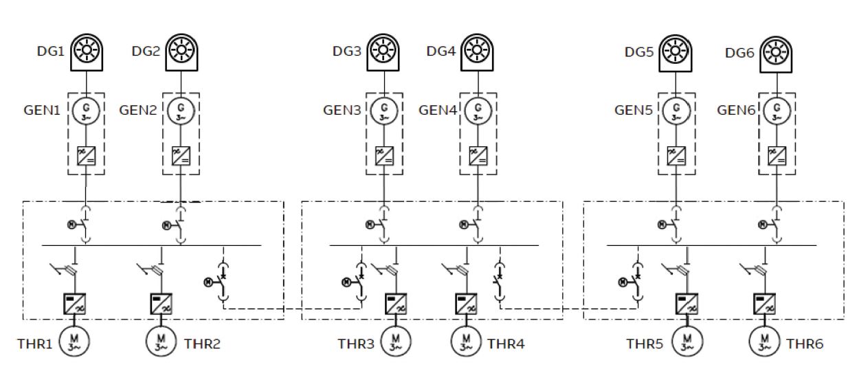
The measured inputs to this particular twin model are:
- Electrical generator power, measured for each electrical generator
- Diesel engine speed
- Fuel consumption for each diesel engine
Other inputs are:
- SFOC (Specific Oil Fuel Consumption) curves for the diesel engines, Madsen (2014)
- Model of the PEMS™ (Power & Energy Management System) function with corresponding limits
One missing component when evaluating and benchmarking fuel consumption is a digital twin in its most literal sense – a digital model of the considerations made by the crew when operating the vessel. There may, for instance, be valid reasons for operating with an extra generator online during an operation, even though it degrades performance with respect to fuel consumption.
In this case, the digital twin model was constructed in several iterations, where the first one was related to the quality of collected signals. After assembling the model and performing the initial analysis, it became evident that the sampling rate of most of the signals were high enough to monitor transit/steaming mode, but insufficient for monitoring of DP operations. The DP system follows the dynamics of the wind, current and waves, which means that sampling needs intervals of seconds, not minutes. This issue was solved by performing modifications to the on board diagnostic system, by adjusting the sampling rate of selected signals. The second iteration covered the signals selected themselves. A DC grid system can be operated with both opened and closed bus-tie breakers, which influences how the individual engines and thrusters are loaded. The status of these breakers was not included in the initial set of logged data and had to be added at a later stage by interfacing the onboard automation system.
A third iteration replaced the initial SFOC curves provided by the manufacturer of the diesel engines with empirical SFOC curves extracted from over a year of operations. This yielded a more accurate image than the generic curves. It also corresponded to the principle stated by Cabos and Rostock (2018), that the digital twin should be updated if the physical object changes.
Completion of this stage of the digital twin then paved the way for more interactions and iterations. Firstly, the twin enables benchmarking and measuring of the operation of the vessel, which can be used as feedback to the crew on board. This may be reflected in the future operations, which again will be measured by the digital twin.
In addition, the digital twin has been used with other modules to simulate the theoretical performance of a modified or slightly different system. For instance, how much energy could be saved by adding an energy storage to the system in Figure 6. This question can be answered quite accurately by combining the digital twin with other simulation modules, such as an energy storage module and a PEMS™ module. This serves as an example of how the digital twin itself enables iterations and system modifications, and the twin model would of course need to be updated after retrofitting the vessel with energy storage.
Use case: condition monitoring of rotating equipment
The deployment of digital twins in rotating machinery such as motors and generators, can provide predictive analytics on faults or performance reduction. Customers can make educated decisions on whether this scenario is acceptable within their current operations or if maintenance needs to be planned.
When the Remote Diagnostic System triggers an alarm, a predetermined maintenance plan can be actioned. The equipment can then be taken offline at a time and place that is convenient for the ship, as opposed to unplanned reactive maintenance that is typically more expensive and operationally costly.
Another case where it was necessary to introduce the iterative process of updating behavioral and configuration aspects of the digital twin also related to a vessel with the power and propulsion system symbolically presented on Figure 7. This time, the main analytics related to condition monitoring of the main rotating electric machinery, consisting of 6 electric generators and 3 selected tunnel thrusters. In the initial approach, well proven methods for machine condition assessment based on spectral analysis of vibration and current measurements were used. Additional sensors such as accelerometers and Rogowski coils were then placed on the machine to measure vibration and electric current with high sampling rates (12,5kHz).
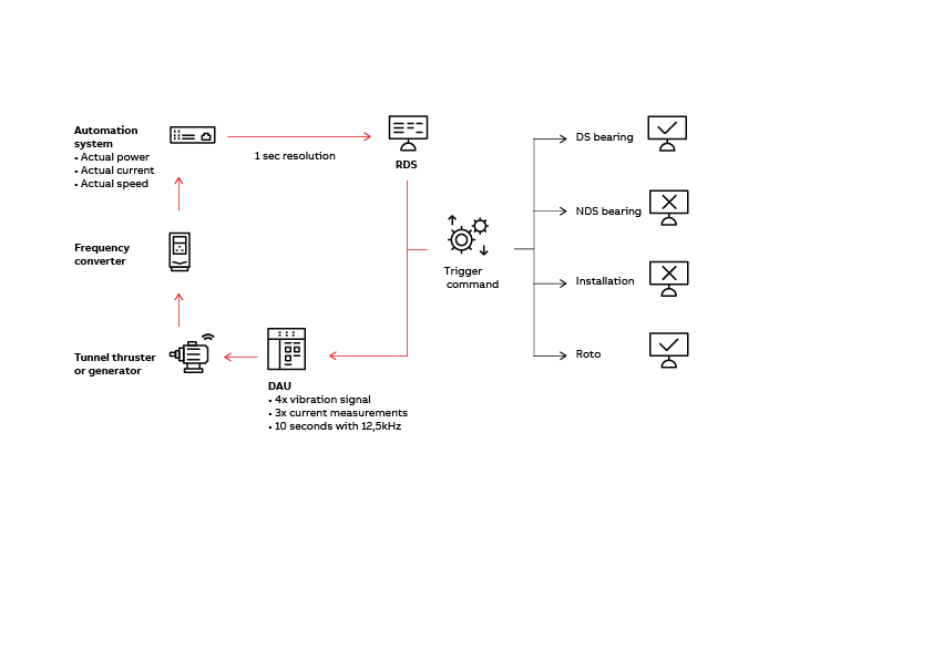
The original data collection and diagnostics scenario assumed that high frequency sampled measurements of vibration and current would be performed once per day at a maximum, working on the basis that the rotating speed of the monitored machine was stable during the high frequency measurement and the load of machine exceeded levels predefined in the system (for instance more than 60 percent of nominal load). These requirements were needed because:
- To perform effective automatic fault identification based on the vibration or current spectrum, the corresponding spectrum must be distinct, and this can be achieved only if the variation of the speed is as low as possible.
- To analyze trends based on specific indicators derived from the spectrum, we should expect at least one measurement point per day to catch dynamics of mechanical faults that may develop in the machine over weeks.
- The higher the load on the machine the better the signal to noise ratio, and thus the higher the reliability of the automatic diagnosis.
There is a certain limitation in the measurement system described, i.e. although vibration and current are sampled with a high sampling rate of 12.5 kHz for the duration (of, e.g. 10 s), the rotation speed itself can only be acquired once per second. This is because there has no additional tachometer installed and the speed is acquired from the automation system using the OPC communication protocol described in chapter 3.2.1. High frequency sampled measurements of vibration and current together with average speed and load calculated while high frequency sampled measurements were taken arrive at the diagnostic system and are checked against calculation criteria; the average load must exceed the threshold level and the variance of the speed must not exceed the specific level. In case the criteria are fulfilled, input measurements are processed using multiple analytics from the domain of signal filtering, spectral analysis and harmonics matching and checked against the warning limit. Very final information is presented to the users on board graphically with traffic lights corresponding to different machine faults (see Figure 8).
The scenario presented has been successfully implemented on numerous vessels and has proved very effective, especially for typical propulsion motors, AC generators or direct online motors. However, in the case under discussion, it was quickly discovered that the way data covering the vessel’s tunnel thruster motors were collected and pre- processed before actual analysis could be improved because the tunnel thruster motors were mainly used in the DP mode. Analysis of the speed and load measurements derived from the digital twin showed speed variations that could exceed 50% within 10 s duration (Figure 9). This was mainly an effect of wave impact compensation while keeping station. In consequence, even though the diagnostic system was triggering the measurements hourly, measurements were not further processed as they did not fulfil preconditions related to minimal speed variance. As a result, main indicator trends contained very few points and did not allow machine experts to give reliable diagnoses and worthwhile recommendations on maintenance actions.
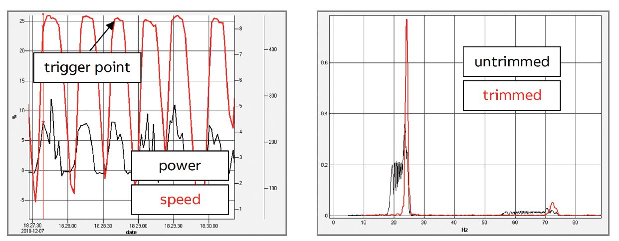
In the first step of iterative improvements the emphasis was put on increasing the number of measurements. This was achieved by changing the condition scenario. Instead of checking the level of speed variance once per hour, the diagnostic scenario checked every second whether the motor was at peak acceleration within a single work cycle. Measurements were triggered immediately to establish whether this condition had been fulfilled (see trigger point, Figure 9). As a result, multiple measurements were taken daily. However, many of them contained the high to low transition speed falling edge, representing a speed variance that had to be taken out of the analysis. This would not have been known if the analysis was based only on low resolution time stamp measurements of speed. The solution was found by analyzing data sampled at high frequency. By analyzing the frequency of supply current wave, the time window for measurement could be cut for most stable speeds, as long as enough time was available to fulfil spectrum resolution requirements and speed variance. Once the window start and end point had been derived using an optimization algorithm, the same time coordinates were used to cut out the corresponding window for vibration measurements (as all vibration and current channels were sampled simultaneously by the DAU – Data Acquisition Unit).
After trimming the high frequency sampled data in this way, they were further processed through the same analytics as was used in the initial deployment. The right-hand chart if Figure 9 shows the vibration spectrum before (black) and after (red) trimming. It is clear that the spectrum derived from trimmed data has a much more dominant main harmonic; thus fault identification analytics is to be more reliable.
The last iteration of the digital twin modified the baseline method and offered proper calculation of warning limits. In the original approach, warning limits were based on initial, single baseline measurements acquired from monitored machines in the early stage of their lifetime. Warning limits were also checked against international standards such as ISO 10816-3:2009 (2009). However, this approach proved inaccurate because one part of its measured values such as velocity RMS multiple times lower than the warning limit given by the ISO standard, while the variance of calculated vibration indicators for each measurement point during the first few months of the machine lifetime was so high that it could exceed baseline limit derived from a single measurement. As a result, the digital twin produced false alarms that were both confusing and undesirable on board. High variance of resulting indicators again originated from high dynamics in the motors’ operating profile and even though diagnostic system checked criteria for the load range, measurement captured instances of extremely high energy that exceeded baseline warning limits.
Here, the was to include statistical variance in the baseline and in the warning limit calculations. Instead of using single measurement as a baseline, a larger set of measurements have been taken into the analysis.
The time range to collect such samples was set at half a year and, with an average of 4-6 measurement points per month, a good set of approximately 30 observations was logged. Following recommendations given by MOBIUS INSTITUTE (2017) for statistical alarm calculations and based on the assumption that vibration indicators spread follows normal distribution, the alarm limit was calculated as a function of the average value and its standard deviation. It is important to note that this new approach was applied individually to each machine, which resulted in different values for the warning limits that corresponded to actual and observed energy vibration levels specific to each machine.
The entire analysis described above has been performed using an on shore digital twin as it is much easier to manipulate data, experiment with different equations and scale the analytics engine in the cloud. Since the core of the on shore digital twin is based on the same software infrastructure as the one on board, updating the behavioral definition of the onboard twin was a matter of a single operation performed using a remote connection.
Summary
The marine industry is currently going through an accelerated process of digital transformation. A very stimulating and open-minded environment has been created where all key players in the market - ship owners, shipyards, system vendors and integrators – are willing and trying to collaborate, integrate and exchange information and data to solve various challenges together. In such an environment, there is a common and strong belief that building digital twins is a fundamental step forward that will add value and eventually result in measurable business gains. By demonstrating how digital twins were used in specific use cases, and the multiple lessons learnt when integrating models, we hope to have highlighted that the marine digital infrastructure must be in place for the iterative and to some extent continuous process of improvement required by digital twins can flourish. From the business perspective investments will be required both by customers and vendors, followed by continuous, advanced service efforts.
References
CABOS, C; ROSTOCK, C. (2018), Digital Twin or Digital Model?, 17th COMPIT Conf., Pavone, pp.403-411
ISO 10816-3:2009 (2009), Mechanical vibration – Evaluation of machine vibration by measurements on non-rotating parts – Part 3: Industrial machines with nominal power above 15 kW and nominal speeds between 120 r/min and 15000 r/min when measured in situ
ABB MARINE (2017), RDS4Marine Engineering Manual software version 5.2.3, manual MOBIUS INSTITUTE (2017), CAT III Vibration Analysis training, online training course
MADSEN, K. E. (2014), Variable Speed Diesel Electric Propulsion, Technical report, Pon Power