ABB’s validated simulation models accurately reproduce entire HVDC Light substations and associated wiring. EMC investigations can be performed reliably during the design, commissioning and operation phases – increasing uptime and reducing costs.
Didier Cottet, Bernhard Wunsch ABB Corporate Research Baden-Dättwil, Switzerland, didier.cottet@ch.abb.com, bernhard.wunsch@ch.abb.com; Göran Eriksson ABB Corporate Research Västerås, Sweden, goran.z.eriksson@se.abb.com; Wojciech Piasecki ABB Corporate Research Cracow, Poland, wojciech.piasecki@pl.abb.com; Gustaf Sandberg, Jenny Skansens ABB Grid Systems, HVDC Ludvika, Sweden, gustaf.sandberg@se.abb.com, jenny.skansens@se.abb.com
The electromagnetic compatibility (EMC) of new products is determined to ensure that equipment, typically sensitive electronics, operate as intended in the electromagnetic environment encountered. Concurrently, devices conducting current shall not emit unacceptable levels of electromagnetic energy or cause interference to other equipment or electronic devices located nearby or at a specific distance. In a typical workflow, experts build product prototypes and measure the electromagnetic radiation in dedicated anechoic or reverberation chambers. Nowadays, large EMC test facilities exist that accommodate entire aircraft. There are no such possibilities for HVDC Light® substations or medium- and high-voltage facilities. Instead, laborious, costly EMC measurements are made on-site after commissioning. Performing measurements at this late stage drastically limits options for implementing design changes if EMC problems arise during fulfillment of requirements. In addition, electromagnetic disturbances from other sources are often present on-site: this can lead to strongly distorted, unreliable results.
ABB, a pioneer in HVDC Classic® for more than 60 years, introduced HVDC Light technology in 1997. Currently, HVDC Light has an important role in renewables, providing a transmission capacity of up to 3000 MW. Ever oriented toward the future, ABB applied advances in numerical methodology to address EMC design at the earliest possible stage of HVDC Light converter station project development. ABB’s smart simulation models, or digital twins, reproduce the entire converter stations including valves, valve hall, converter reactors, wall bushings, converter transformers, high frequency (HF) filters and the entire wiring in the AC- and DC-yards. Digital electromagnetic twins allow a wide range of EMC related investigations to be performed reliably during the design, commissioning and operation phases:
• Impact of semiconductor switching on HF disturbance characteristics
• Control algorithms and system dimensioning (ie, cell voltage and current ratings)
• HF filter optimization and positioning
• Design variants for components, component placement, bus bar and cable layout
• Shielding effectiveness of building construction
Substation model – the digital twin
In 2014, ABB initiated a project to model a HVDC converter station using CST Microwave Studio® (MWS), a commercial, numerical electromagnetic (EM) full-wave tool. Particularly useful for rapid accurate analysis of high frequency components, CST MWS allows 3D modeling of systems, sub-systems and components, including buildings and HV buses →1.
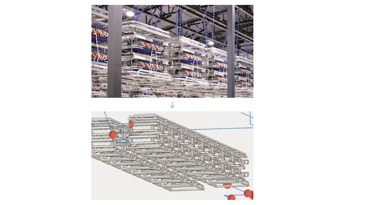
Station components such as instrument transformers, breaker and power conversion functionalities, converter topology, and switches, are connected to the 3D model in a dedicated schematic view. This function allows rapid and accurate visualization of the complex models →2.
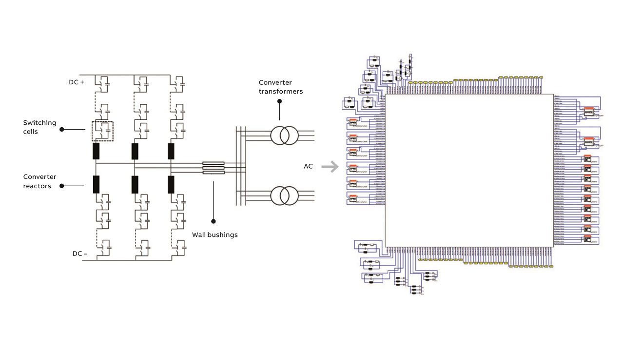
Modeling methodology
The CST simulation environment, which is embedded in a dedicated, systematic workflow, consists of procedures and tools for creating component models for the pre-processing stage and for analyzing the simulation result during the post-processing stage. All models and sub-models can be created at an early design stage, typically significantly earlier than when physical components are actually available – a crucial advantage.
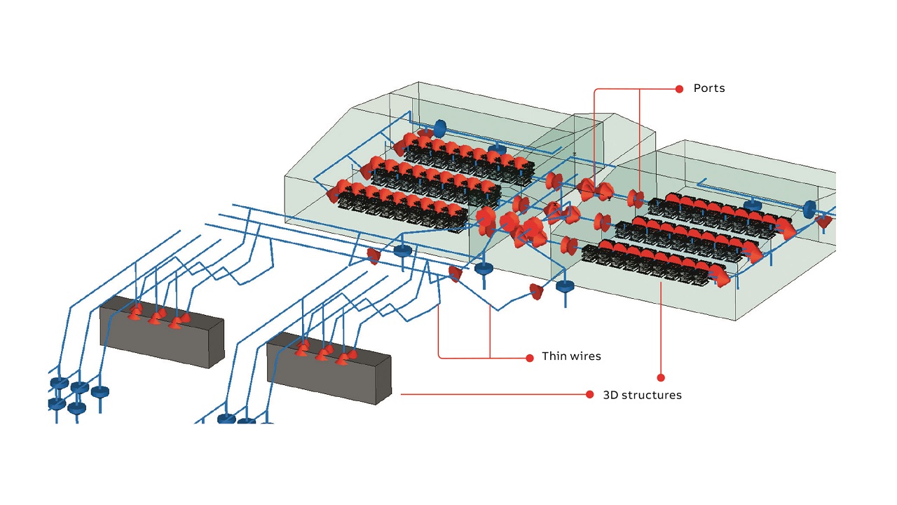
The system-level model of the entire station is excited →3 at the different physical locations where the actual HF disturbance is generated. A voltage impulse function is injected that results in the propagation of HF currents within the station.
The resulting impulse response of this time domain simulation can be transferred to the frequency domain, thus gaining a broadband system response spectrum, which can be garnered for various observation points eg, H-field probes, and current probes. Next, the impulse responses can be convoluted with the actual converter switching waveforms and processed with an electromagnetic interference receiver detector model. The results are directly comparable to values obtained by measurements of the electromagnetic radiation at an existing converter site.
ABB employed a transmission line matrix solver with specific features that are particularly well-suited for this type of simulation. The 3D models support a combination of 3D structures and so-called thin wires that have much smaller cross sections than the mesh element size usually used →3. Furthermore, component boundaries for apertures, slots, etc. can be defined to effectively simulate shielding properties of enclosures and valve-hall wall-types typically installed by utilities. Finally, lumped circuits can be added to the 3D model where more complex circuit sub-models of components can be connected via user-defined ports. Here lumped circuit elements and complex netlists can be connected. By combining various types of representation of particular elements of the system, complexity is reduced and simulations are more time-efficient.
Nevertheless, to be a powerful tool, simulations must accurately reproduce the high frequency impedances of components in the AC- and DC-yard of the stations eg, converter reactors →4, converter transformers, wall bushings and instrument transformers. In-depth information about system and component modeling justifies its use in converter station modeling [1,2].

04a An air core reactor. 
04b The resultant simulated magnetic field pattern of a similar phase reactor is shown.
04 High frequency impedances of an air core reactor are reproduced beautifully.
Validation
To influence product realization, intelligent modeling relies on physical measurements. ABB performed extensive high frequency measurements at the component and system levels that validate the simulation results, thereby affirming the fitness of the twin →5.

05a Validation of an HVDC transformer. 
05b EM radiation measurements are made at near-field inside an AC yard. 
05c EM radiation measurements are also made at far-field, located 200 m from the converter station.
05 ABB’s model is validated through high frequency measurements of equipment and components.
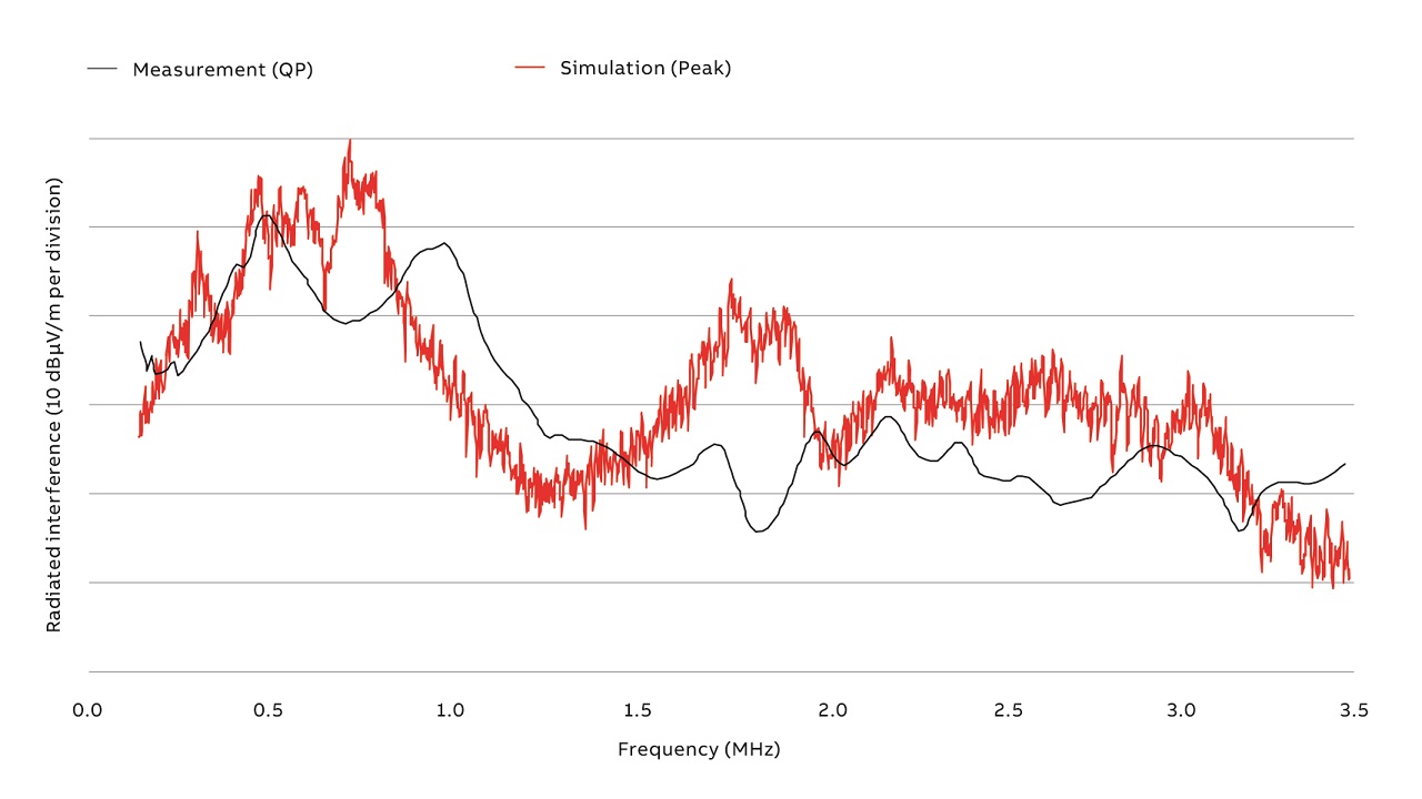
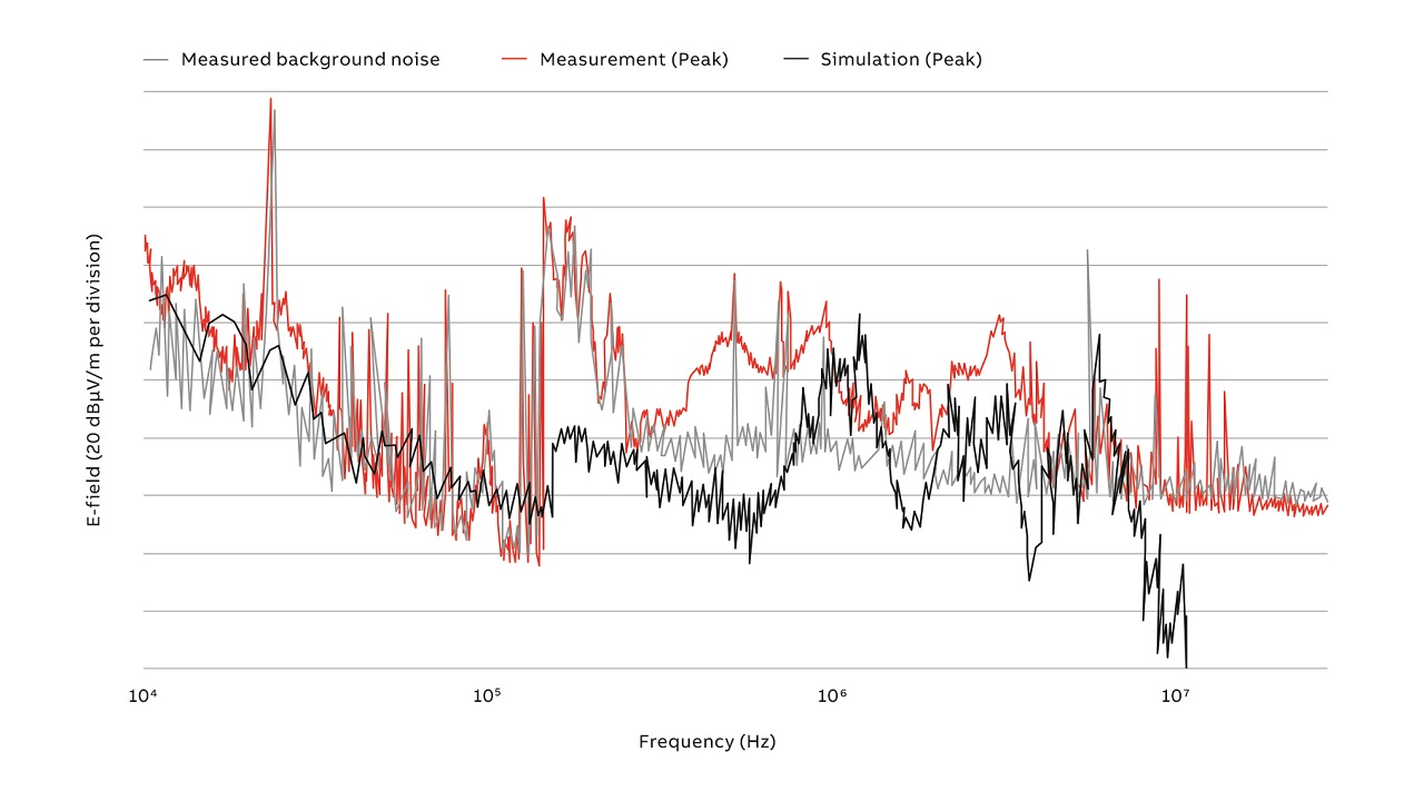
The measured and simulated HF disturbance in the near-field (within the AC yard close to the HVDC converter) →5b and far-field, (at a position of 200 m from the AC yard) →5c are in excellent agreement in terms of the predictability of critical peaks →6.
Design advantages
Electromagnetic compatibility design and performance is effected by many system-level parameters. ABB not only meets all EMC challenges, but it improves EMC. A simulation model enables utilities to make crucial EMC design choices at the earliest possible stage. The ability to optimize early rather than late results in significant cost reductions and lower downtime. This contrasts with the highly problematic task of implementing changes once critical on-site measurements have been made. Such changes, if at all possible, are associated with huge costs and require operations to be shut down for necessary reconstruction.
Additional applications
Because aspects of EMC design include filters, shielding and switching characterization station layout, apparatus design, and grounding system, etc, ABB applied EMC simulation models to these products, processes and systems to enhance availability and reliability →7.
EMC filter design
Product success often depends on how quickly a product reaches the market. EMC filters are crucial for this process: The best possible filter design can save time during certification and reduce production costs. ABB investigated the optimization of EMC filter design with regard to filter equipment and filter placement in an HVDC converter station. The simulated magnetic field at 5 MHz for the initial filter solution was designed without the help of 3D simulations →8a and compared with that of a 3D-model aided design. Not surprisingly, the 3D-model optimized filter displayed a significant reduction in field amplitude →8b.

08a Magnetic field distributions before optimization of the HF filter design. 
08b Magnetic field distributions after optimization of the HF filter design.
08 Magnetic field distributions in an HVDC converter station were tested.
Furthermore, similar field-level reductions were seen across the entire frequency range investigated. More importantly, in one case the use of the 3D simulation model resulted in lower costs and significant performance improvement. ABB’s smart 3D-model enhanced filter design performs better, at a potentially lower cost. Most significantly, the level of detail made available from the 3D simulation enables recognition of possible EMC issues in the future – performance predictability is possible.
In today’s fast-paced environment of tenders and projects, decisions for novel solutions often need to be made on the fly. Models that closely approximate their physical product or plant twin greatly facilitate the ability to make key decisions rapidly – supplying value to an enterprise.
Building design and on-site installation done properly and efficiently, early, add great value. Shielding, in particular, is of paramount importance to business value. Buildings function to prevent strong direct emissions, which emanate from the valve structure, from reaching the outside world. For an HVDC converter building, bushings, doors, vents etc, are necessary for the converter to function but will reduce the shielding efficiency of the building because they create openings in the EMC shield or Faraday cage. Moreover, metallic wall cladding eg, overlapping sandwich panels with aesthetic, practical surface treatments, are usually free from electric contact. The inclusion of a seemingly small window can reduce the effectiveness of the shield by orders of magnitude in an otherwise perfectly designed building. Currently, 3D simulation models provide the best opportunity to optimize shielding requirements early and translate the requirements into practical details, thereby reducing the risk of costly and time-consuming modification work on-site at a later phase. Shielding requirements can also have a strong effect on radiated interference →9.
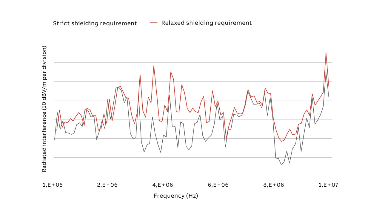
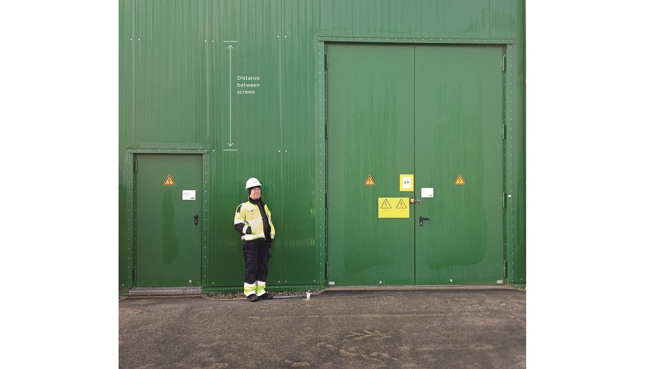
Accordingly, ABB ran two simulation models on the shielding of the valve hall: one with strict requirements and another with relaxed requirements →9. The distance between screws provides the electrical connection between wall panels →10. For strict shielding requirements, this distance is an order of magnitude less than for relaxed requirements. The greatest differences are found above a threshold frequency of about 2–3 MHz →9. These results, together with EMC requirements and deep knowledge of the susceptibility of equipment to electromagnetic disturbance located close to the power station, can enable utilities to make better decisions about shielding requirements.
Even though modeling examples are taken from HVDC applications, the same EMC simulation methodology can be applied to other medium- and high-voltage applications introduced by ABB eg, FACTS, SVC Light® and Rail SFC Light®. ABB, with its long-term commitment to innovation in the power sector, will continue to introduce innovation like the HVDC Light digital twin technology to change how products are created, realized and evolve. ABB’s ability to perfect EMC demonstrates commitment to customers. Improving power station uptime by increasing the availability and reliability of critical components and systems that might affect electromagnetic performance is just one way ABB accomplishes this today.
Acknowledgments
This article would not have been possible without the ideas, effort and dedication of the entire project team and stakeholders. The authors would like to extend their special thanks to:
Filip Grecki, Arne Schröder, Pawel Kryczynski, Szymon Piela, Magdalena Ostrogorska, Celine Tigga and Olof Andersson.
References
[1] D. Cottet, G. Eriksson, M. Ostrogorska, J. Skansens, M. Wunsch, F. Grecki, W. Piasecki and O. Andersson, “Electromagnetic modeling of high voltage multi-level converter substations,” in Proc. of the Asia-Pacific Intl. Electromagnetic Compatibility (APEMC) Symposium, Singapore, 14–17 May, 2018.
[2] B. Wunsch, D. Cottet, G. Eriksson, “Broadband models of high voltage power transformers and their use in EMC system simulations of high voltage substations,” in Proc. of the Asia-Pacific Intl. Electromagnetic Compatibility (APEMC) Symposium, Singapore, 14–17 May, 2018.