Internal arcing in oil-filled transformers can have catastrophic consequences. Designed using a numerical methodology, ABB’s TXpand solution, which includes optimized tank design and safer component selection, can mitigate the effects of most internal arcing events.
Samuel S. Brodeur ABB Inc. Varennes, Canada, samuel.s.brodeur@ca.abb.com; Huan M. Dinh ABB Inc. Lexington, KY, United States, huan.m.dinh@us.abb.com
Oil-filled transformers are critical power network components that operate continuously in harsh conditions. Although low – at around 1 percent per transformer service year [1] – the rate of major failures among these transformers is not insignificant, especially as the consequences of failure (major oil spills, fire and collateral damage) can be catastrophic.
A low-impedance internal arc in oil-filled electrical equipment heats and vaporizes the surrounding oil to create a gas bubble. This effect is not the same as a chemical explosion, which requires an explosive mixture of fuel and oxidizer. For this reason explosion prevention systems, such as the rupture discs commonly used in petrochemical applications, are rarely used in transformers.
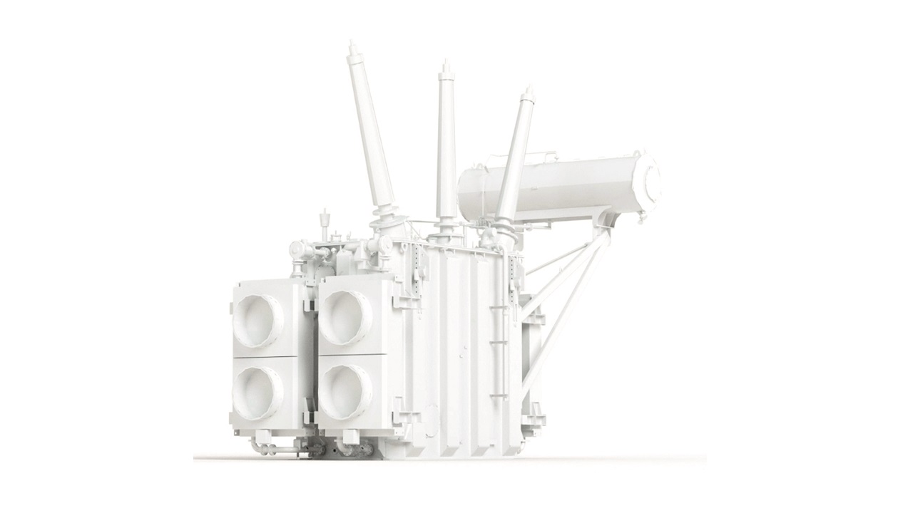
ABB has specifically developed and optimized the TXpand solution to mitigate the effects of internal arcing in transformers →1.

TXpand
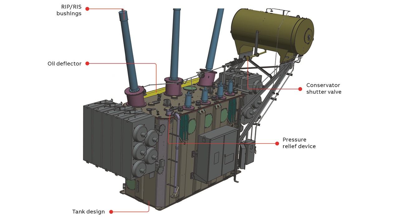
A fire-risk mitigation strategy should consider several electrical protection measures, the most important of which is the inclusion of a fast-acting circuit breaker to limit fault duration and, therefore, the amount of energy injected into the fault zone. Mitigation must also encompass a transformer design that complements the electrical countermeasures. TXpand has five such measures →2.

Tank design
A Hydro-Québec survey on their 735 kV network reported that in 50 out of 74 major failures, tank rupture was the main cause of oil spill and, thus, fire risk [2]. This type of hazard can be managed by the rupture-resistant tank design proposed here. The philosophy is to contain a specified arc energy by absorbing the fault energy in a plastic deformation of the tank. The corresponding tank design is the core of the TXpand solution. TXpand has been developed by careful analysis and modeling to make the most rigid areas flexible and the weakest points stronger. Strategic rupture points allow the most unpredictable failures to be controlled.
RIP/RIS bushings
Oil-impregnated paper (OIP) bushing failures cause the most fires following a transformer internal fault [1]. The Hydro-Québec survey mentioned above showed these bushing failures to be the second main cause of oil spill (18 cases out of the 74 failures) [2]. The use of resin-impregnated paper (RIP) or resin-impregnated synthetics (RIS) bushings can mitigate the risk of major oil spills, fire and porcelain shattering during internal arcing.
Conservator shutter valve
The conservator shutter valve is installed on the oil pipe connecting the conservator and the tank. The valve allows oil flow in both directions but it will close and initiate an alarm if the flow rate exceeds a certain limit. In the case of bushing failure or main tank rupture, the shutter valve should prevent oil spilling from the conservator and feeding a fire.
Pressure relief device (PRD)
A PRD is a spring-loaded valve used to vent the internal pressure after the arc energy has been consumed by the tank deformation. A pipe is installed at the outlet of PRD to guide the oil and gas away appropriately to the base containment system.
Oil deflector
The fifth of the transformer design mitigation measures concerns the strategic rupture point, which is designed to be at the transformer cover weld. Because a hot oil/gas mixture could be ejected for a short period, an oil deflector can be installed on the strategic rupture points to divert the stream and prevent spills impacting the safety of personnel →3.

03a Normal situation. 
03b With ejected oil flow deflected.
03 By directing it onto and down the tank external wall, the oil deflector prevents ejected oil endangering personnel.
What is behind the tank design?
Arcing in oil has been studied for many decades and much has been learned about the science of the phenomenon. For example, it is known that the arc energy depends on the maximum current available, the arc duration (which is short if the electrical protection is efficient) and the arc voltage. From a case recorded on the Hydro-Québec 735 kV system, a pressure effect of the surrounding gas bubble on voltage was observed [3] and a more accurate equation was proposed to calculate the arc voltage, the most evasive of the parameters to measure.
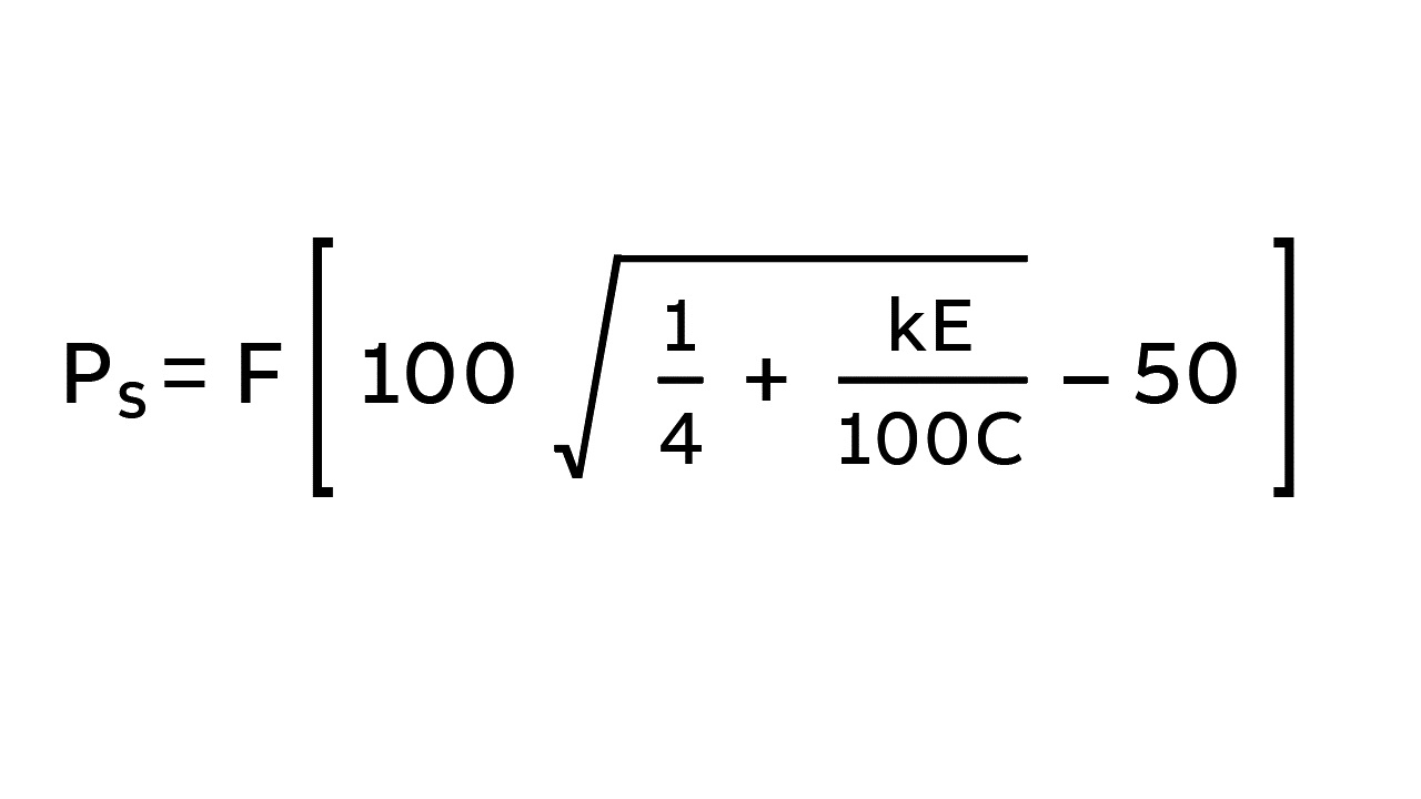
The chemical composition of the arc has been under investigation since 1953, mainly for circuit breaker applications. The authors of five published studies agree that the arc gas generation rate is linear and the temperature in the reaction zone is about 2,000 °K [1]. In an extensive experimental program on distribution-type transformers in conjunction with numerical simulations, it has been concluded that a gas-to-volume conversion factor of 85 cc/kJ at standard temperature and pressure matches reality well [4]. This arc gas generation is used in the following expression to characterize the pressure built up in a transformer tank [3]. The equation has a dynamic amplification factor that is a ratio of the localized dynamic pressure to the final steady pressure. This dynamic effect was observed in transformer experiments with chemical explosions in special vessels [5] and an extensive numerical experimental study with high-pressure injection [3].

Ps: calculated tank pressure (kPa)
E: fault energy level to withstand (kJ)
k: arc energy conversion factor (5.8 x 10⁻⁴m3/kJ)
C: tank expansion coefficient (m3/kPa)
F: dynamic amplification factor
A good understanding of the science of the tank itself is critical. The importance of the tank expansion coefficient on the internal tank pressure was first realized in 1959, during experiments on oil-filled rectangular transformer tanks subjected to sudden discharges of nitrogen, and was simultaneously confirmed by numerical studies [6,7]. However, tank resistance characteristics were virtually unknown so, in 2011, Hydro-Québec and ABB launched an extensive investigation into this topic. In over five years of research, a numerical methodology was developed to analyze transformer tank behavior in the plastic domain, up to the rupture point. These numerical results have been validated in around 40 destructive experiments. All numerical parameters, such as the geometry simplification, mesh size, element type, contact element, boundary conditions and results analysis were calibrated via this experimental process. These years of learning yielded numerical simulations that gave accurate displacement results and, therefore, the expansion coefficient of the tank – and, ultimately, tank strength characteristics →4.

04a Displacement (tank flexibility.) 
04b Strain (global strength evaluation.) 
04c Critical regions (tank rupture points.)
04 Tank numerical analysis process.
Large power transformer test
A full-scale 330 kV, 210 MVA transformer equipped with a mock-up active part was designed and manufactured according to the TXpand design rules [8]. This water-filled tank was subject to an injection of pressurized air equivalent to the gas produced by a 20 MJ arc energy in oil. This high energy release is, to ABB’s knowledge, the highest such ever reported. The tank expanded as predicted by ABB’s numerical simulations and the tank absorbed all the energy injected without any rupture →5. The PRD took more than 5 s to release the tank internal pressure, which is rather slow in comparison to a three-cycle fault duration (50 ms).

05a Before internal fault event. 
05b After internal fault event.
05 330 kV transformer tank pressure test.
In a second test, a higher pressure was injected, with the intention of causing a tank rupture. Even if the gas bubble is created at the bottom of the tank, the tank ruptures at the strategic rupture point predicted by the numerical simulation – eg, the tank cover weld.
SSVT transformer test
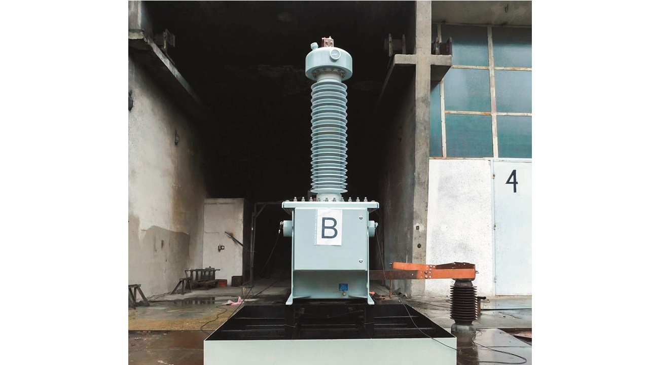
The TXpand simulation techniques – developed for power transformers – were applied to a 650 kV BIL (basic impulse level) station service voltage transformer (SSVT), which has an internal tank volume one-hundredth that of a power transformer. The analysis led to several design changes to improve tank resistance against internal arcing. In 2017, a full SSVT assembly was tested with an internal fault current of 40 kA for 300 ms according to standard IEC 61869-1 2007 for the highest protection level (stage 2 and class II) →6. The SSVT successfully passed all test requirements: the tank resisted the pressure, no ejecta or fragmentation was observed and oil was evacuated by the PRDs within about 5 s. This experiment demonstrated that the powerful numerical methodology developed for large power transformers can be scaled down for SSVTs.

TXpand is simple, efficient and cost-effective
The TXpand solution is based on a numerical methodology, a deep knowledge of arcing gas generation and many years of research and development. Experiments on both large power transformers and SSVTs have demonstrated the efficacy of TXpand. From collaborations with customers, TXpand has been seen to be simple, efficient and cost-effective. ABB now has a proven technology that significantly mitigates the consequences of a transformer internal arc event. A safer transformer could also be used as a starting point from which a cost and risk review of the costly substation base oil containment system could be initiated.
References
[1] Cigré, “Guide for Transformer Fire Safety Practices – Working Group A2.33,” Cigré – Technical Brochure 537, 2013.
[2] M. Foata, “Power Transformer Fire Risk assessment,” Cigré, Sydney, Australia, 2008.
[3] M. Foata and J.-B Dastous, “Power transformer tank rupture prevention,” Cigré, Paris, 2010.
[4] J.-B Dastous and M. Foata, “Analysis of Faults in Distribution Transformers with MSC/PISCES-2DELK,” MSC World User’s Conference, Los Angeles, 1991.
[5] T. Kawamura et al., “Prevention of Tank Rupture Due to Internal Fault of Oil Filled Transformers,” Cigré session, Paris, 1988.
[6] M. Foata and G. Khouzam, “Power Transformer Tank Rupture,” Canadian Electrical Association, Engineering and Operating Division, Toronto, 1994.
[7] R. E. Kothmann and D. G. Thompson, “Power Transformer Tank Rupture: Risk Assessment and Mitigation,” EPRI, 1995.
[8] S. Brodeur and J.-B. Dastous, “Design and Testing of an Arc Resistant Power Transformer Tank,” IEEE Transactions on Power Delivery, 2019. (Paper still in review by IEEE.)