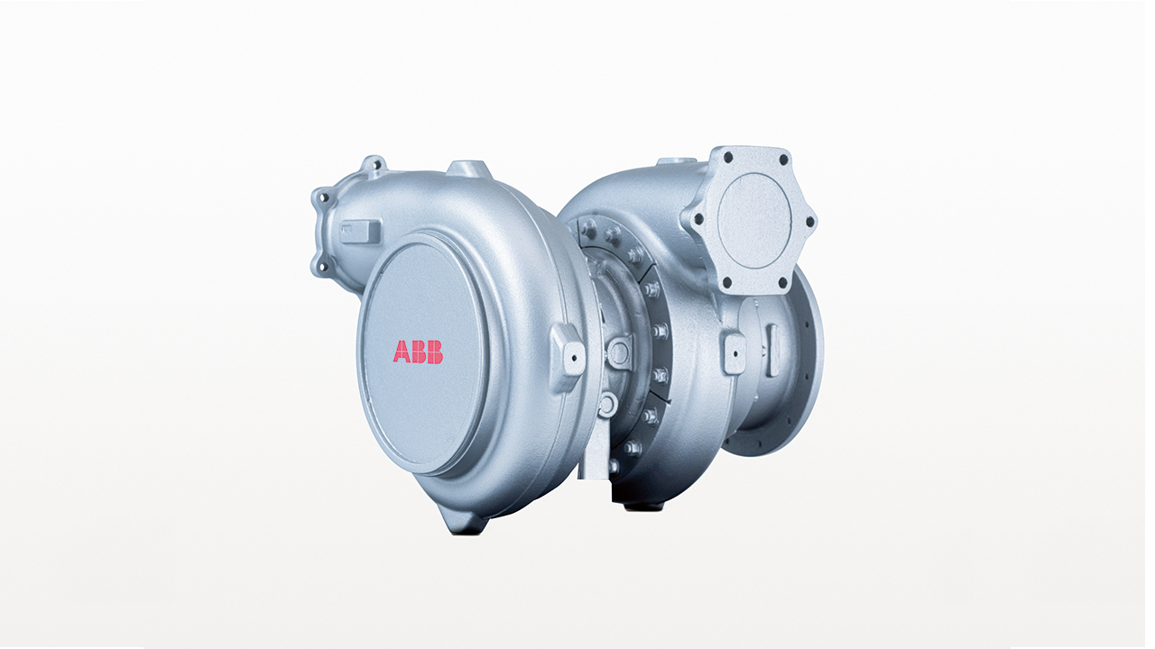
To fill the gap between ABB’s A100-H single-stage turbocharger and Power2® two-stage turbocharger, ABB has developed the A200-H. With a pressure ratio of up to 6.5 and peak efficiency over 69 percent, the A200-H enables single-stage turbocharging on high-speed gas engines with a brake mean effective pressure of 24 bar.
Gerald Müller, Antje Hertel, Franco Domenig, Martin Seiler, Florian Maurer ABB Turbo Systems Baden, Switzerland, gerald.mueller@ch.abb.com, antje.hertel@ch.abb.com, franco.domenig@ch.abb.com, martin.a.seiler@ch.abb.com, florian.maurer@ch.abb.com
Driven by demand for decentralized, flexible, cost-effective and environmentally friendly power generation, lean-burn, high-speed gas engines have become a mainstay of the modern power generation landscape. Over the last 20 years, an increase in brake mean effective pressure (bmep) of approximately 1 bar every three years has been observed in these engines, while electrical efficiencies have increased significantly over the same period. This evolution has, in turn, driven the need for turbocharger pressure ratio and efficiency improvements.
With its current single-stage turbocharger generation, the A100-H, ABB defined the state-of-the-art limit for single-stage turbocharging with pressure ratios up to 5.8 and a turbocharger efficiency of up to 66 percent [1]. The A100-H accommodates lean-burn gas engines with a bmep of up to 22 bar. For higher bmep, advanced two-stage turbocharging was successfully introduced to the gas-engine-based power generation market about 10 years ago and has shown convincing operation results ever since. ABB’s Power2® two-stage system, for example, offers excessive pressure ratio reserves and efficiencies of over 73 percent – at the cost of additional complexity, weight and expense over single-stage solutions. For gas engines that operate at a bmep of between 22 and 24 bar, two-stage turbocharging is potentially too complex a solution and full utilization of the potential of Power2 requires a bmep level of over 24 bar.
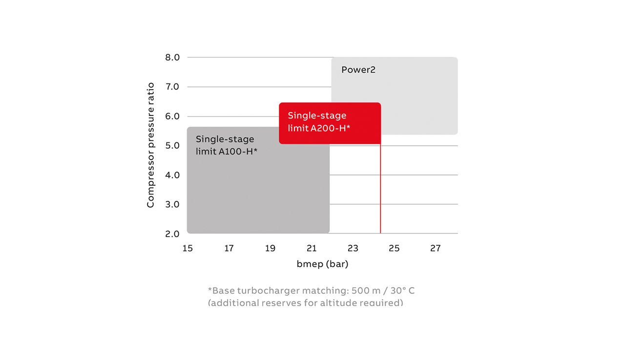
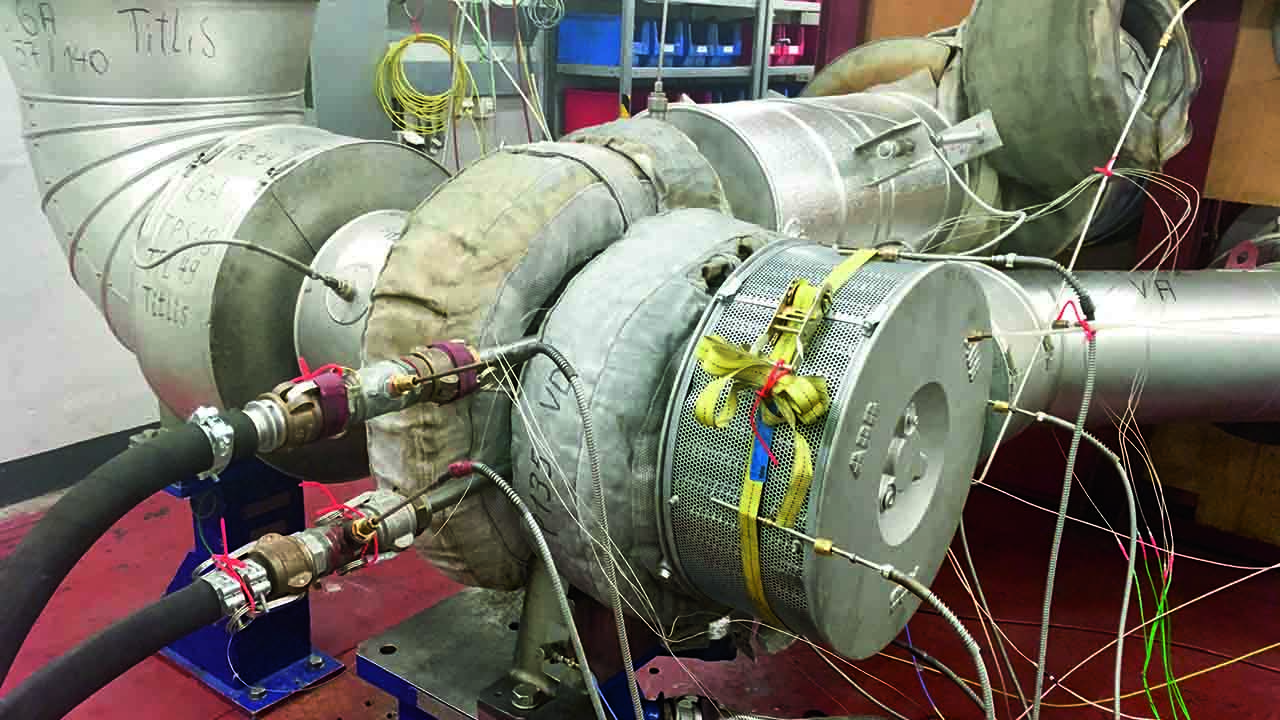
To fill this gap between single- and two-stage turbocharging and thus enable high-speed gas engine manufacturers to continue development work aimed at increasing power density or supporting high-altitude applications, ABB has developed the new A200-H, with a pressure ratio up to 6.5 and a peak turbocharger efficiency in excess of 69 percent →01, 02. The A200-H enables single-stage turbocharging on high-speed gas engines with a bmep of approximately 24 bar while at the same time increasing engine efficiency compared to the A100-H.
Turbocharger efficiency
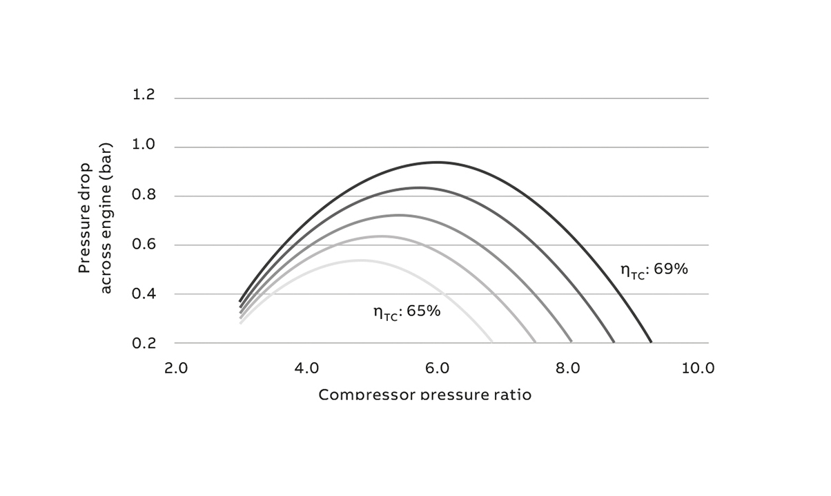
→03 shows that a higher pressure ratio requires a higher turbocharging efficiency to keep the pressure drop across the engine (pressure in the receiver minus pressure before the turbine) constant. It was as a result of these engine requirements that the development targets for A200-H evolved: increased pressure ratio capabilities and at the same time higher turbocharging efficiency compared to the current A100-H turbocharger series.
Compressor-stage concept
The turbocharger specific flow rate had to be optimized for the requirements of a high pressure ratio and high efficiency level. Freedom was given to make some dimensions larger than those on the A100-H. Nevertheless, the single-stage configuration still offers simplicity and compactness compared to a two-stage turbocharging solution. The use of a compressor stage with an aluminum alloy impeller allows advantage to be taken of efficient manufacturing processes that enable the required high quality standards. With regard to the challenging thermodynamic target, the aluminum alloy impeller should offer exchange intervals of 40,000 running hours (which may be exceeded by exploiting a digital solution, see below).
Compressor map optimization
→04 shows that the achievable pressure ratio for nominal engine operation is well above 6 for the A200-H. Stable operation of the engine requires a sufficient margin for the operation line in relation to the compressor surge line. Therefore, the compressor map is not only optimized to match the efficiency requirements but is also optimized with respect to the compressor map width. A special focus was the operation range, with pressure ratios up to 6.5 made possible by applying up-to-date map width enhancement technology [2]. An improvement of 70 percent in map width could be achieved compared with the A100-H reference stage.
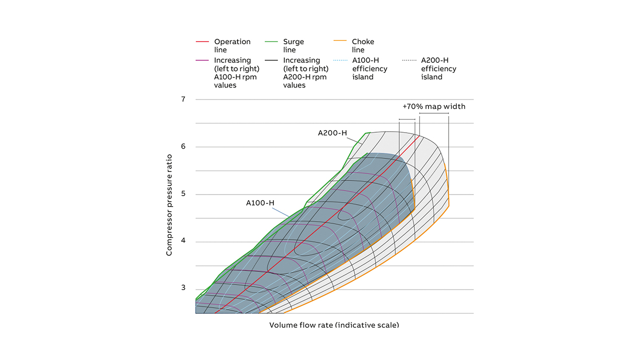
In keeping with the proven concept for ABB turbochargers, adjustment to the required volume flow will be possible through a range of compressor wheel trims.
Compressor mechanical qualification
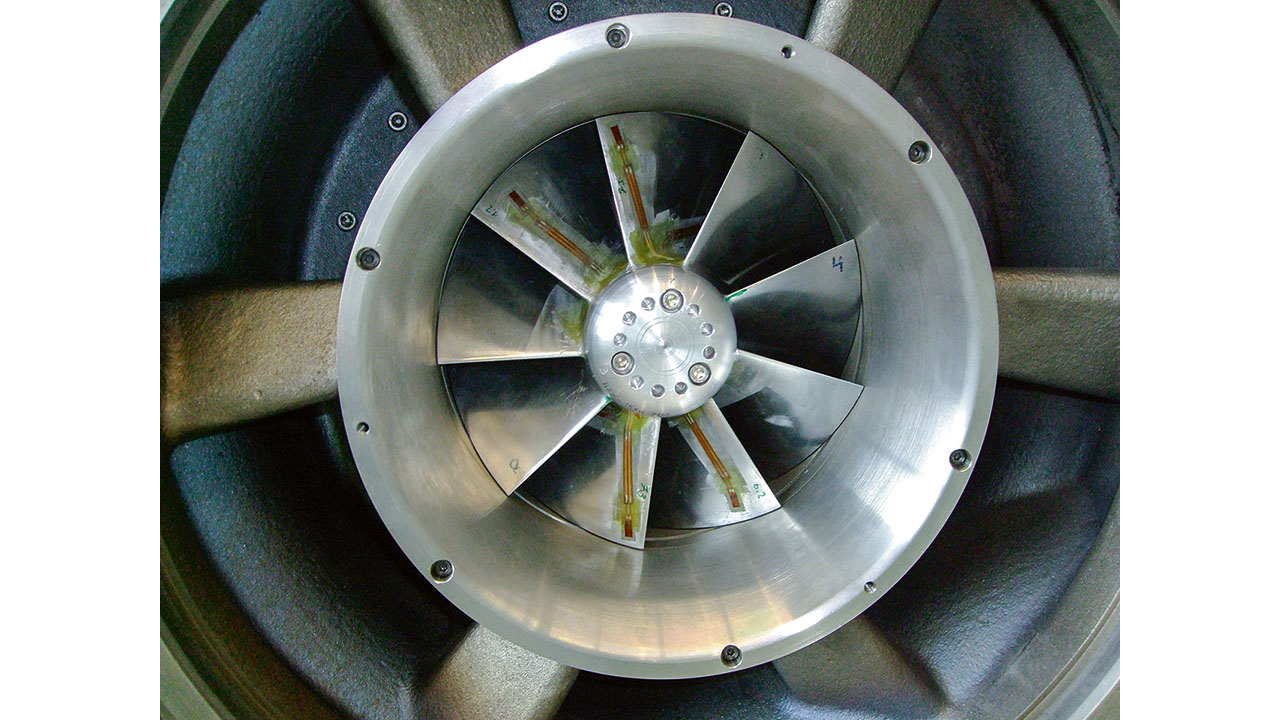
The compressor stage is mechanically designed to withstand the excitation of eigenmodes in the operating range. Finite element (FE) analyses coupled with ABB’s in-depth knowledge of blade vibration behavior allowed targeted design measures to be taken to either reduce potentially critical resonance amplitudes or to make excitations disappear. The result is a robust design in terms of high cycle fatigue but with a minimum number of qualification loops. The FE analyses also allowed the targeted placement of strain gauges during the qualification procedure →05.
Turbine stage
A new turbine stage has been developed to cover the high compressor pressure ratios of up to 6.5 with a high turbine efficiency. The turbine has been matched to the compressor to get the highest possible turbocharger efficiency while meeting the mechanical requirements. All the turbine components – gas inlet, nozzle ring, turbine wheel and diffusor – were designed according to the necessary flow range and pressure ratios. 3D computational fluid dynamics (CFD) was extensively used to ensure high performance and mechanical integrity for the high speeds involved was ensured by FE analysis. The necessary component lifetime and recommended exchange intervals for gas engine applications can be met despite the high speeds.
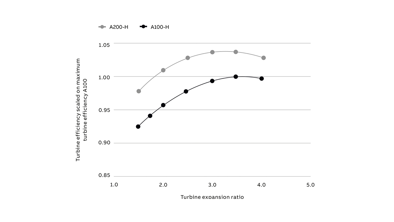
In combination with the high-pressure compressor, a turbocharger efficiency of over 69 percent could be reached in a technology demonstrator →06.
Housing design
A drop-in design for the air and gas connections was given up in order to focus on the required high performance level. With this new degree of freedom, the air and gas connections were repositioned and extended. An advantage of this reconfiguration is better accessibility of the turbocharger’s connecting points and, consequently, considerably easier handling during assembly and service.
With a view to future peak-shaving applications, housing stress optimization had to be taken into account at an early design stage. Advanced FE tools were used to, for example, model an improved turbine casing for engine starts that quickly lead to high gas inlet temperatures and to ensure a high number of start-stop cycles can be accommodated.
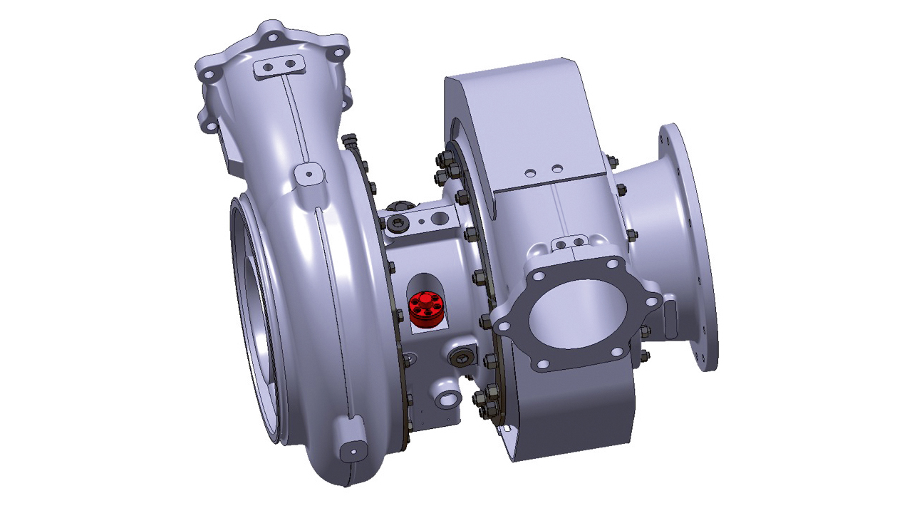
Further, experience with the A100-H generation revealed that mounting larger turbochargers on the engine console would be easier either with hydraulic fastening or with clamping nuts. Hence, the new A200-H turbochargers offer both options →07.
Shaft and bearing system
As with today’s radial turbochargers, the use of plain bearings, supported by a squeeze oil damper in the bearing flanges, is the most reasonable option in terms of cost and operational reliability for the new A200-H turbocharger generation. To ensure easy assembly with as few parts as possible, the thrust main and auxiliary bearings are positioned on the compressor side.
The A200-H series lets customers, for the first time, choose between two bearing concepts for the same turbocharger. The A200-H includes a patented bearing module design that supports ABB’s plain bearings as well as newly developed and highly efficient ball bearings →08. At part load, power loss for the ball-bearing option is around 15 percent that of the plain bearing option, which makes it the perfect choice for customers with highly transient operation modes. Transient thermodynamic simulations based on a popular 2 MW gas engine and different propulsion concepts demonstrated a time-to-full-load decrease of about 15 percent (hot start and cold start) just by exchanging the bearing system for ball bearings.
Both bearing designs are directly connected to the standard engine oil circuit. No additional measures are necessary for the ball-bearing option, but oil consumption as well as heat dissipation into the oil is halved compared to the same turbocharger equipped with plain bearings. The single-module ball-bearing design makes the upgrade from plain bearings easy.
Lower lifecycle costs with digital capabilities
Rotor lifetime depends on turbocharger speed and temperature as well as on the number of load cycles. In the past, certain ambient conditions – with defined deviations – and an operation profile were assumed and a conservative approach to the allowable operational parameter values taken. However, cyclic operation – for peak shaving, for instance – is now on the increase. This regime subjects engines and turbochargers to a much higher number of start-stop cycles than in the past. Not only the mechanical load cycles but also the severe temperature fluctuations have a major wear impact.
The digital capabilities of the new A200-H series now offer more flexibility regarding the assessment of turbocharger maintenance needs and the release of operation limits beyond today’s recommendations. Monitoring of turbocharger speed and temperatures, start-stop cycles, ambient conditions and other parameters will be introduced with turbocharger-integrated sensors or with access to data from the genset system. The access to installation-specific operation data enables an exposure-based component life assessment, ie, a review of rotor component lifetime consumption and a check of hot static parts that is based on operation history.
An online analysis of collected data allows an assessment of the shaft and rotor components with every inspection, eg, after each 20,000 running hours interval for natural gas applications. If the analysis of operation data permits it, the customer will get a “good to go” for the next inspection interval with full warranty. At the 40,000-hour inspection, customers can opt to receive an extension of the recommended exchange interval beyond the 40,000 hours dictated by the rigid and conventional approach that exists without continuous digital support. Assuming a full engine lifetime of 120,000 running hours, with one major overhaul during that period, the potential extension of the rotor exchange interval will allow the operator to run the turbocharger with only two rotors over the engine lifetime – ie, to exchange the rotor only once, thus reducing cost.
For hot static parts under cyclic thermomechanical fatigue (TMF) load, the acquisition of operating data and the correlation with wear and tear behavior of the parts gives new insights and expands the existing experience base significantly. A new analysis algorithm and the latest optimization tools in the design process will allow further TMF-optimized designs of casings and other parts that are prone to severe thermomechanical loads. Future peak-shaving applications will benefit from the new digital offerings with further extended application limits and considerably reduced lifecycle costs.
Having the digital solutions for A200-H on board offers even more opportunities and added value for A200-H turbocharger operators. Maintenance scheduling, performance trend monitoring, fleet management and timely upgrade advice are some examples of new offerings that will be introduced step by step with the new series.
Timeline and application range
ABB’s next-generation A200-H turbocharger series sets an innovative benchmark in single-stage, high-pressure turbocharging. The A200-H responds to the requirements of high-speed engine builders and operators for increased power density, higher system efficiency and reduced specific lifecycle costs. A200-H turbochargers offer compressor pressure ratios up to 6.5 and turbocharger efficiencies of over 69 percent.
New compressor and turbine stages have been developed to ensure an outstanding performance level, mechanical reliability and a suitable component lifetime in demanding full-load operation. The turbocharger design meets challenging requirements – eg, those regarding cyclic operation, efficiency loss minimization, containment safety and rotor dynamics.
The A200-H’s digital capabilities offer more flexibility in the assessment of turbocharger maintenance needs and the lifetime assessment of components. Installation and operation-specific data facilitate an exposure-based assessment and potential for reducing lifecycle costs significantly. High-speed engine customers are eager to explore the full potential of the new series and the first A240-H prototypes were tested in late 2019. Three smaller turbochargers, A238-H, A234-H and A231-H, will follow to complete the new turbocharger series. Start-up of production of these turbocharger types is planned for 2021/2022.
Reference
[1] D. Wunderwald, et al., “The New A100-H Single-Stage Turbocharger Series for High-Speed Engines,” MTZ worldwide, issue 07-08, volume 69, pp. 9-14, 2008.
[2] L. Galloway, et al., “An Investigation of the Stability Enhancement of a Centrifugal Compressor Stage Using Porous Throat Diffuser,” Journal of Turbomachinery, 140(1), 2017.
