Sampo Viherialehto
Sales Manager and Concept Promotion, Icegoing Vessels
ABB Marine & Ports
Pirjo Maattanen
Senior Engineer, Structural Mechanics
ABB Marine & Ports
Samuli Hanninen
Key Account Director
ABB Marine & Ports
Icebreakers in the historic context
Icebreaking allows the nations of the North to maintain a vital, continuous supply of goods and raw materials through the cold season. In the early days, icebreakers were steam powered. As early as 1933, the first diesel electric icebreakers were introduced, though diesel electric propulsion remained rare outside the icebreaking sphere for decades. With the passing years, diesel electric propulsion has gained momentum. The diesel electric powertrain offers many advantages over traditional mechanical diesel shaft line propulsion, including enhanced power management at speed and more reliable dynamic power handling.
Science, cargo transport or line icebreaking?
In icebreaking, the general operations are generally divided between scientific operations, cargo transport and assistance of merchant marine vessels. Scientific operations are subject to the same environmental conditions as assistance, but without the time pressure of line icebreaking. Indeed, the distinction between icebreaking for science and assistance can be found in the different requirements for efficiency. In line icebreaking, the number of vessels assisted over a period of time is a key parameter. Different sets of realities dictate the different icebreaking duties. In some countries, the annual number of icebreaking assistance cases is less than hundred. In countries dependent on icebreaking, assistance is an ongoing operation, resulting more than 3,000 cases annually. From an operating point of view, there are many similarities between line icebreaking and scientific operations. In both cases, vessels are sometimes required to face consolidated hummocks and ridges. This operational requirement also extends to icebreaking cargo vessels proceeding independently through ice-infested waters.
Responsibility for other vessels
In scientific research, the timeframe for planning the voyage is relatively long. In cargo transport, the charter of goods is always set in a particular time frame. Despite their dissimilarities, there is an even bigger difference between vessels used for these tasks and those used for line icebreaking. A vessel with responsibility only for its own operations demands different capability than a line icebreaker managing ports and vessels, pilotage and VTS functions together. In ship design, it is also important to distinguish whether the vessel will be primarily engaged in assisting other vessels or attempting to complete a voyage independently.
Azimuth thrust
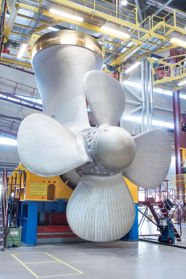
The handling performance of ships remained in many respects static until the introduction of the azimuth thruster. Azimuth thrust increases the efficiency of icebreaking assistance by enabling the ship’s main engine power to be directed 360 degrees. This freedom of power vector application has brought profound change to icebreaking. The main categories in azimuth thrust are mechanical thrusters and electric gearless thrusters. With mechanical thrusters, the electric or diesel motors are located inside the ship’s hull. In this configuration the power is transmitted via axles and bearings to the propeller. With the electric azimuthing thruster, thrust is generated in the pod unit by an electric motor. The electric pod does not require gears to transfer power. These features have made the electric propulsor the leading technology of choice in icebreaking. It has also allowed the unit size to grow into the 20MW range.
Line icebreaking principles
Line icebreaking can be roughly divided in four distinctive tasks, though the sequence may vary depending on direction of traffic. Assuming a vessel is in-bound to port from sea, the operation starts with variable sea ice conditions and moving ice fields at sea. Often the vessel is confined in ice, requiring the icebreaker to first cut her loose. In high wind conditions, the ice field also has a significant pressure component preventing vessel movement. Secondly the vessel must be assisted to the fairway area. In the fairway, assistance is limited by draft and buoyage. When the convoy reaches the port entrance, the icebreaker terminates assistance and port icebreaking assumes responsibility. Azimuth propulsion can play a key role in all the above situations by reducing the time needed for ice management.
Sea ice conditions present icebreaking challenges
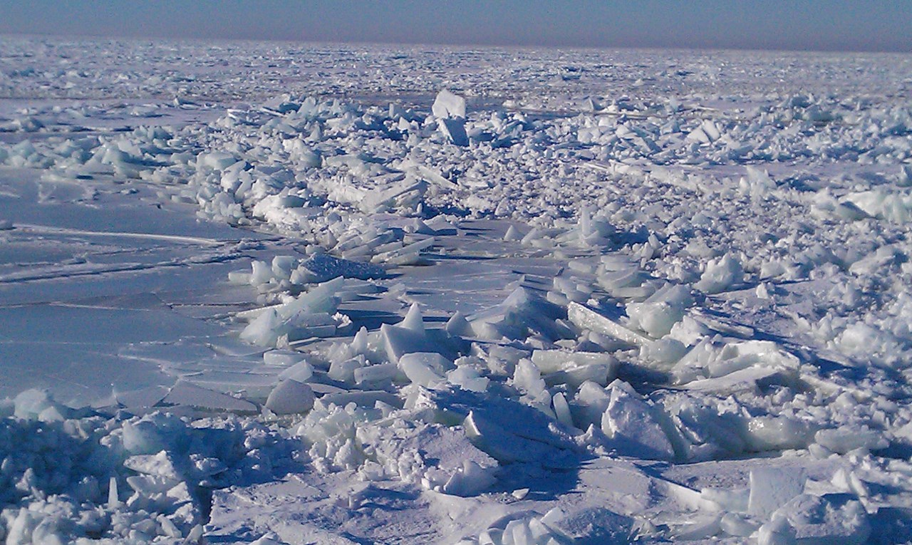
Sea ice conditions vary greatly and are constantly changing, presenting icebreaking crews with unique challenges. For example, sea ice in the Arctic is often a mix of drift first-year ice with multiyear ice inclusions. Ice at sea is in constant motion, and movement tends to range from 0,1Kts to 1,1kts1. When the ice is packed against a land mass or a fixed ice pack, the combination of wind and ice movement creates ice pressure. This pressure in turn forms different ice features. In a level ice field, the pressure begins to crack and bend the ice, creating ridges and hummocks. If the ambient air temperature is well below freezing, the hummocks consolidate and become very difficult to move. At the ice edge where swell and wind work against the ice, the result is different. Here drift ice is ground into shuga and brash ice barriers. If temperatures are well below freezing, the brash ice barrier eventually consolidates into floes that are very difficult to impact.

Track creation width
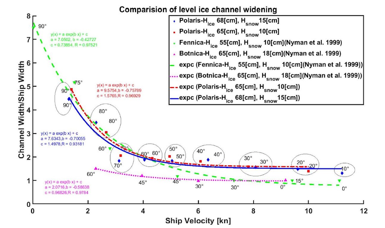
An icebreaker with solid axles creates a track as she forces through the ice. The track width is defined by vessel breadth, ice quality, ice pressure and direction of travel in relation to ice movement. In fast ice with low ice pressure, the track may be 1.5 times the breadth of the icebreaker. In heavy ice pressure the track closes just seconds after the icebreaker has passed. For a merchant vessel to be able to follow the icebreaker the track must be sufficiently wide. As the track closes, the speed of the assisted vessel decreases and the vessel finally comes to a stop. To increase track width, the breadth of the icebreaker must be increased. This however has practical upper limits. Power requirements and fuel consumption grow with the increased size of the icebreaker. Azimuth thrust offers a solution for this problem, enabling the ship’s thrust vector to be directed not only aft, but also to the sides of the ship at an angle. This creates a power vector moving the icebreaker forward, but also creates a wider track. In relative terms it becomes feasible to assist larger vessels and operate in difficult ice fields with increased efficiency. It is often critical to achieve increased track width in order to conclude assistance without stopping. Azimuth thrust enables increased track width and improves assisting efficiency.

A wide channel can also be made by steering the ship at an approximately 40-degree angle sideways. This oblique icebreaking is possible with icebreakers equipped with aft and bow mounted azimuth thrusters. Oblique icebreaking creates an ice channel at least twice the width of the ship.

Cutting vessels free
Cutting loose a vessel beset in ice requires operations at close quarters. In heavy ice conditions this is done with high power output. Together, these factors contribute to a high risk of collision. Azimuth thrust increases the maneuverability of the icebreaker many times. Turning circles are decreased and overall control is increased.
Ice pressure can create dangerous conditions where ice floes begin to climb up the side of the ship. In these conditions the icebreaker makes safety circles around the beset vessel to alleviate pressure. In these conditions the increased maneuverability due to azimuth thrust enables making closer and faster safety circles.
The mode of operation differs between icebreakers with solid axle lines and azimuth thrust, when cutting ships loose. With solid axles the icebreaker moves along the beset ship at very close quarters and cuts close in front of her bow. At the moment of passing, the icebreaker instructs the beset vessel to make full ahead. When in front of her bow, the two begin to move as a convoy. The icebreaker leads the way and adjusts the distance between the vessels according to ice conditions. When the ice pressure increases, or ridges form choke points, the vessel is escorted at very close proximity to the icebreaker, sometimes only a few meters apart. Azimuth thrust changes these sequences by allowing the icebreaker to pass by and flush the ship free by manipulating the thrust vector toward the beset vessel. By eliminating the need to move in front of the bow, it is also possible to flush loose multiple vessels sequentially. Convoy assistance with azimuth thrust also differs from the example above. With azimuth thrust, the icebreaker can adjust to the prevailing ice pressure and choke points incrementally by spreading the thrust vector. This allows greater distance between the vessels, improving safety and reducing the risk of collision in case of a sudden stop due to unexpected ice features.
Azipod® full-scale ice load measurement
The first azimuthing podded propulsors for ice going ships were launched in the 1990’s. Due to the novelty of the concept, no information or guidance about azimuthing propulsor ice loads was available. Ice loads needed to be measured in order to verify dimensioning loads.
The first measurements showed that dimensioning was conservative, as expected. This does not mean that structural dimensioning should be lightened. Ice loads vary greatly depending on ship type and operation area. Over the years, propulsors in different ice going ships with high ice class – supply vessel, cargo vessel, and icebreaker – have been instrumented for ice load measurements. Load calculation and dimensioning methods including power and propeller torque usage can be verified to cover a wide range of propulsors in different ships, providing solid tools to develop reliable higher power equipment.
The latest ice load measurements were conducted on the Finnish icebreaker Polaris’ propulsors. The ship is equipped with a three-pod solution, with 6 MW Azipod® unit at the bow and two 6.5 MW units at the stern. Polaris is the first icebreaker with a propulsor unit at bow, and offers excellent opportunities to compare ice load distribution between stern and bow propulsors.

Polaris has been in operation in the Bay of Bothnia for three winters, 2017-2019. Ice conditions were so mild in 2020 that Polaris was not required to perform icebreaking duties. Operational experience thus far indicates that the maximum measured loads for bow and stern propulsors were about 40 % of design loads.
Design ice loads for the bow propulsor were 25 % greater than for the stern propulsors, which corresponds well to longitudinal measured loads. Bow propulsor ice loads are slightly higher for longitudinal direction that for stern propulsors, and stern propulsor side loads are correspondingly higher for side direction. This is as expected, since stern propulsors are operated more often in different steering angles and receive ice hits from the side. The bow propulsor is mainly at zero angle when proceeding in ice at high speeds. Increased design loads for bow propulsor side ice load are therefore not necessary.

ABB ice load dimensioning principles for the Azipod® propulsor has been well proven, with 30 years of ice operation. In addition to full-scale load measurements, dimensioning has proven to be safe, since no ice-induced damage of propulsor or propeller has been documented.
Based on the long-term measurements, it can be concluded that a Polaris-type icebreaker can operate without speed or other operational restrictions in all Baltic Sea ice conditions. This includes ramming operations in ridged ice fields in the Bay of Bothnia.
Another article in this edition of Generations reviews onboard energy storage system for icebreaking (Title, page no.). Long-term measurement data from IB Polaris were further used to simulate the benefits and enhanced operational performance with the aid of a battery pack.
The development of Polaris was closely followed by several icebreaker operators. After Polaris, the Russian energy giant Gazprom Neft ordered two icebreakers “Alexander Sannikov” and “Andrey Vilkitsky” based on a similar ship concept. Gazprom Neft operates the Noviy Port oil fields on the Yamal peninsula in demanding ice conditions. To support operations close to the Arctic loading terminal, two highly maneuverable icebreakers were needed, and the Polaris concept proved to be a perfect fit. Power was increased to two 7.5 MW Azipod® units in the stern and a single 6.5 MW Azipod® unit in the bow. The ice class was also increased to Russian Maritime Register of Shipping Icebreaker 8, the second-highest RMRS IB class, corresponding to IACS PC2. Both vessels were delivered in 2018, and operational experience thus far has been highly positive.
The North Pole and beyond
The Norwegian Coast Guard vessel KV Svalbard, Figure xx, is the first ever Azipod® powered ship to reach the North Pole, another milestone demonstrating the capabilities vessels with Azipod® propulsion.
In August of 2019, KV Svalbard, built in 2001 and equipped with twin 5MW Azipod® icebreaking units, became the first Norwegian vessel to sail to the North Pole. The ship travelled through packed polar ice at speeds as high as six to seven knots as part of an international scientific expedition, the Coordinated Arctic Acoustic Thermometry Experiment (CAATEX), led by the Norwegian non-profit research foundation The Nansen Center.
Latest developments
The changes in ice concentration and reach in the Arctic have allowed for increased vessel traffic. Where many operations were not feasible in the past, they now are. This is the result of ice conditions lessening in severity, and technology moving forward. The VI series Azipod® has been a key factor in enabling Arctic shipping to grow. A good example is found in Arctic offshore oil and gas activity. To be economically feasible, vessels must be able to operate without continuous icebreaker assistance. Azipod® VI has provided the necessary bollard pull levels, but perhaps more importantly the capability to navigate the vessel stern-first through consolidated ridges and hummocks.

References
ABB. (2019, 12 17). Azipod® Gearless Propulsion. Retrieved from Azipod® – State-of-the-art gearless propulsion: https://search-ext.abb.com/library/Download.aspx?DocumentID=3AJM0050000051&LanguageCode=en&DocumentPartId=&Action=Launch
ABB Inc. (2019). Propulsion Technology for Sustainable Polar Shipping. ASNE Arctic Day. Washington: American Society of Naval Engineers.
Australian Antarctic Division: Leading Australia’s Antarctic Program. (2019, 12 17). Retrieved from Shipping Schedule for 2019/20: https://secure3.aad.gov.au/public/schedules/voyage.cfm
Azipod® gearless propulsion. (2019, 12 17). Retrieved from Benefits of Azipod® propulsion: https://new.abb.com/marine/systems-and-solutions/azipod
Clare, H. (2017). Icebreaker. London: Chatto & Windus.
Dufour, S. (2019). Coast Guard Update A/Regional Director, Navigational Programs, CCG, Central and Arctic Region. Canadian Marine Advisory Council Prairie and Northern Region. Yellowknife.
G. H. Taimuri, P. Kujala. Aalto University; T. Leiviska, Aker Arctic; Pirjo Maattanen, ABB. (2018). Level ice Clearing in Model and Full Scale Using Azimuthing Propulsion. Arctic Technology Conference, 2018.
Hovilainen, M. (2014). Next Generation to Break the Ice -The Oblique Icebreaker. OTC Arctic Technology Conference. Houston: Offshore Technology Conference.
Huoltovarmuusorganisaatio. (2018). Merenkulun huoltovarmuus. Retrieved from – TOIMINTAYMPÄRISTÖN: https://cdn.huoltovarmuuskeskus.fi/app/uploads/2019/01/14160416/Merenkulun-huoltovarmuus.pdf
Keinonen, A. (2008). Ice Management Experience in the Sakhalin Offshore with Azimuth Icebreakers. Icetech 2008, (p. 6). Banff, Canada.
Riska, K. (2020, 1). UNESCO - Encyclopedia Life Support Systems (UNESCO-EOLSS). Retrieved from http://www.eolss.net/Sample-Chapters/C05/E6-178-45-00.pdf
The first diesel-electric icebreaker in the world. (2019, 12 17). Retrieved from Scandinavian Shipping Gazette: https://archive.ph/20130809053724/http://www.shipgaz.com/old/magazine/issues/2003/04/oldship_0403.php
Vainio, J. (2002). Sea Ice Nomenclature. Helsinki: Merenkulkulaitos.
VTT. (2016). VTT-CR-03151-17_Polaris_ice_Trials.
VTT. (2017). VTT-CR-00587-18_Polaris_season_report_2017.
VTT. (2018). VTT-CR-04121-18_Polaris_season_report_2018.
VTT. (2019). VTT-CR-00870-19_Polaris-season_report_2019.
Wärtsilä. (2019, 12 17). Diesel-electric propulsion. Retrieved from Wärtsilä: https://www.wartsila.com/encyclopedia/term/diesel-electric-propulsion
