Elham Attar, Magne Saxegaard ABB Electrification Skien, Norway, elham.attar@no.abb.com, magne.saxegaard@no.abb.com; Nitesh Ranjan, Jan Carstensen Former ABB employees
Environmental concerns related to the global warming potential of SF₆ are promoting a new generation of gas-insulated switchgear (GIS) based on environmentally friendly insulating gases. In this switchgear, vacuum switching technology is used for the LBS and much research effort has concentrated on the dielectric and thermal challenges [1, 2] this technology poses. Vacuum switches are also costly and require an additional disconnector switch, which includes a complex drive mechanism.
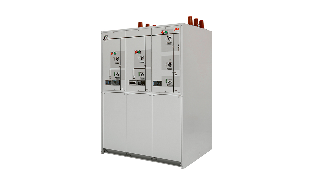
Refined puffer interrupter technology promises a reliable, cost-effective and easy-to-use LBS alternative →01.
Puffer interrupter technology for eco-efficient insulation gas
The puffer interrupter consists of a compression chamber and an interruption chamber →02. The principle of operation is to “blow out” the arc by using the overpressure generated by compression of the gas by the piston. The compressed gas is released into the arcing zone, where it cools the arc ignited between the contacts. The arc is extinguished at the first current zero (CZ) crossing if the contact distance and cooling achieved is sufficient to withstand the transient recovery voltage (TRV). The TRV arises from magnetic energy trapped in the inductances on the load side of the circuit breaker, where it gives rise to a current that circulates between the capacitances and inductances there. This current can generate a transient overvoltage. The difference between the voltage potential upstream of the breaker and these transient overvoltages gives the TRV.

SF₆ is very suitable as an insulating gas in switches due to its intrinsic capability to both cool the arc and quickly restore the insulation level after the switching event. Replacing SF₆ with eco-efficient alternatives in a puffer interrupter reduces interruption performance both in the thermal and dielectric phases (see following two sections) due to inferior arc-quenching properties and lower dielectric strength of alternative gases.
ABB has designed a puffer interrupter that overcomes these challenges posed by eco-efficient gases. Significantly better interruption performance in SF₆ alternatives is achieved by creating a so-called stagnation-point flow pattern of gas around the arcing zone. Further, because weak dielectric strength in both cold and hot zones in the LBS may cause restrikes, innovative solutions have been implemented to tailor the flow pattern of the hot gas to prevent arc re-ignition. Although interruption capability is the main challenge, the functionality of a new LBS also has an optimized dielectric and thermal design. Advances made in these respects allow a compact LBS to be created that uses eco-efficient insulation gas alternatives while maintaining the established ratings and footprint of SF₆ GIS.
Thermal interruption
Different topologies of the flow around an interrupter arcing zone are shown in →03. The common flow pattern utilized in SF₆ medium-voltage (MV) puffer interrupters is called “simple flow.” Here, the gas flows straight through the moving contact and nozzle system toward the fixed contact. Experiments with a simple flow puffer interrupter under different gas pressures and loads have indicated that the interruption performance is not sufficient for SF₆-free MV applications [3].
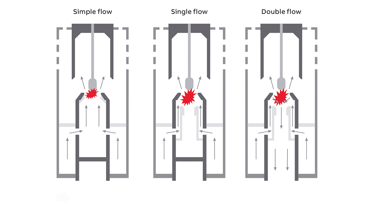
Two alternative designs were explored: Single-flow and double-flow designs, which both feature a “stagnation point” that is found to improve the interruption performance significantly for air compared to the simple flow design →03. A stagnation point is a point in a flow field where the local velocity of the fluid becomes zero and all the kinetic energy is converted into pressure energy. The stagnation-point type of flow is commonly utilized in high-voltage circuit breakers, but no applications are known for commercial MV LBSs.
During the opening operation in stagnation-point type designs, the piston attached to the moving contact compresses the gas, which results in overpressure in the compression chamber. At the same time, the arcing tulip contact is pulled away from the arcing pin, which consequently generates an arc →04. The arc initiation heats the gas, which partly “clogs” the critical cross-section of the nozzle, resulting in an even higher pressure in the compression volume. Eventually, the pressurized gas from the compression volume blasts into the arcing zone and helps to extinguish the arc. The arc extinction should preferably occur at the first CZ crossing, and, therefore, enough gas pressure is needed to blow out the arc at that point. As a part of the new design, customized ports are made around the arcing zone. Fresh gas can then enter via these ports to quickly replace the ejected hot gas.
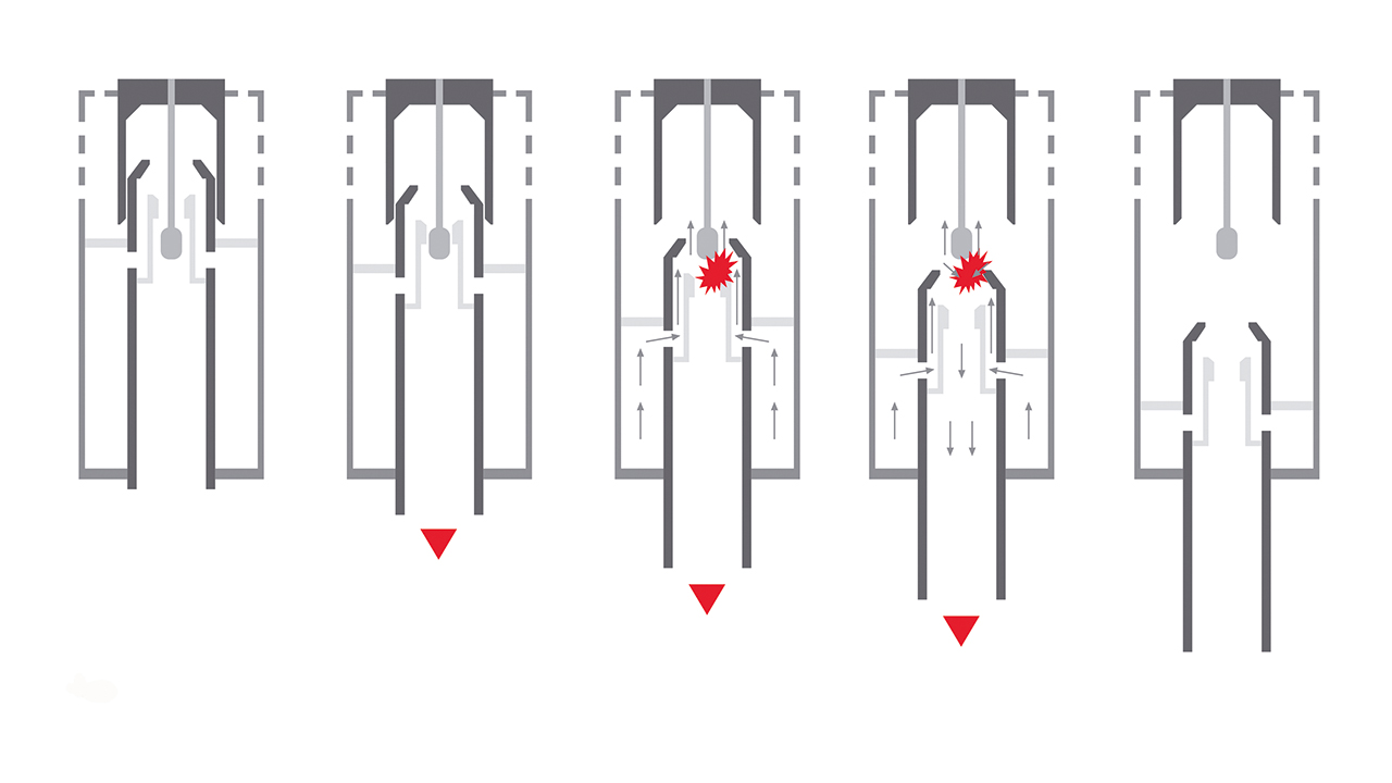
Many parameters of the puffer design influence the gas flow and pressure buildup in the system and lead to different interruption capabilities. In the switching device discussed here, the gas is used as both an arc interrupting and a dielectric medium. The specific arrangement of the flow pattern chosen in the arcing zone significantly improves the interruption performance.
Dielectric restrike
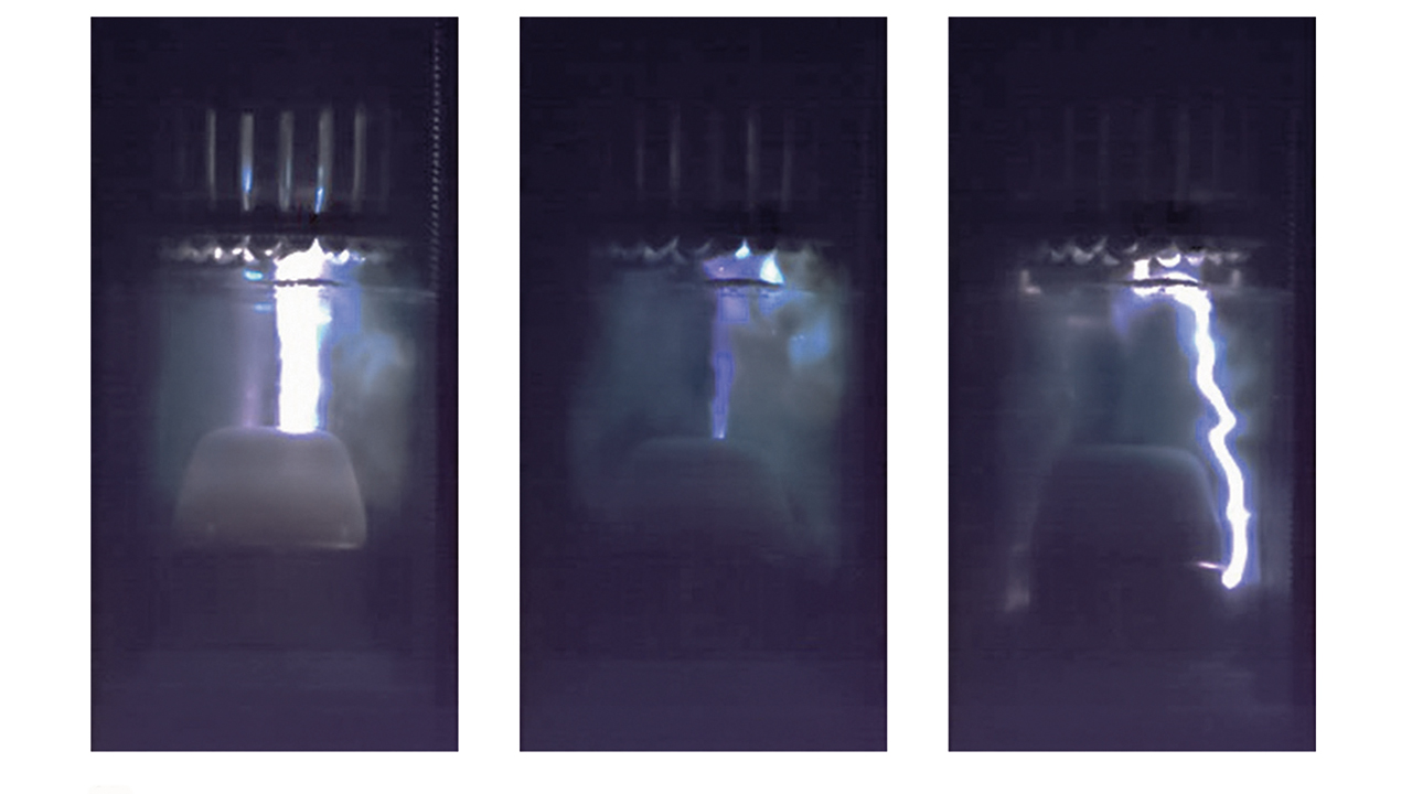
The dielectric phase – around 10 to 100 µs after CZ and characterized by a residual current close to zero – may generate restrikes if a hot gas and metal vapor mixture generated by the burning arc remains around the contacts. This mixture has lower dielectric strength than cold insulation gas and when the TRV increases, restrikes may take place within or away from the original plasma channel. To quantify the robustness of the new switch design in this respect, experiments were conducted at different development stages →05.
In addition to full-scale experiments, computational fluid dynamics (CFD) modeling is another major tuning tool for both root-cause analysis and sensitivity analysis of new switchgear design concepts. →06 illustrates CFD modeling of the cloud of accumulated hot gas around the contacts in the double-flow design for two different arcing times. The ideal situation would be to push this hot gas away from the moving main contact – ie, it is essential to tailor the flow pattern of the hot gas generated during the interruption event in such a way that reignition in the dielectric phase is prevented. The flow pattern can be controlled by splitting the fixed arcing contact (arc pin) and giving the fixed main contact multiple contact members with pressure-release openings. Further, the gas outlets should be large enough to avoid the flow of hot gas toward the main contact and any change in the contacts should not sacrifice the required cross-section of the main current path →07.

06a Arcing time = 5.25 ms. 
06b Arcing time= 13.3 ms.
06 Temperature distribution just after CZ crossing. The arrows indicate the gas that is pushed away.
By implementing some openings on the field controllers around the interruption chamber, the hot gas, vapors and exhaust generated during the arcing event are transported away from regions with high electrical field stress, which not only assists cooling but also helps to maintain the dielectric strength of the gas at the level needed between phases.

07a Double flow. 
07b Single flow.
07 Effect of the outlet at the end of the tube on the accumulated hot gas around the main contact just before the CZ. Double-flow design reduced the accumulated hot gas around the main contact.
Dielectric design
Although the dielectric withstand of air in, say, a ring main unit (RMU) application is almost one third that of SF₆ [3], the footprint of a new air-
insulated switching unit should not be greater. Therefore, substantial effort has been made to reduce the electric field stress near compo-
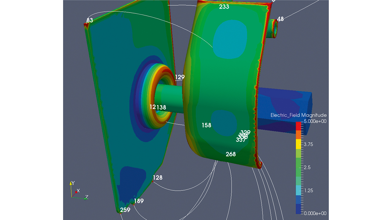
nents [3]. This action has resulted in very smooth parts that are, in effect, field shields →08. Novel designs have been implemented to overcome high-stress regions at triple points, where conductive solid, insulating solid and insulating gas meet [4]. Finally, the sophisticated design of the puffer interrupter fulfilled all dielectric requirements based on common standards such as IEC 62271-1 [5].
Full-scale testing
Full-scale interruption type tests were conducted on a commercially available ABB SafeRing/SafePlus Air unit, according to the “active load” test duty classes E3 and C2 of the IEC standard for a rated voltage of 12 kV at a nominal current of 630 A [6].
A cost-effective and easily operated alternative to a vacuum LBS
Puffer interrupters, which use the gas blast produced by the relative movement of moving and fixed contacts, are widely used in SF₆ switchgear due to their compact size, simple structure and excellent interruption characteristics. In a puffer switch, the interrupting capability depends on the interaction between arc, gas properties, flow pattern, pressure buildup and geometry. The stagnation-point type of flow improves the interruption performance compared to simple flow in non-SF₆ gases. The successful performance of the new interrupter design described here makes it a cost-effective and easily operated alternative to the LBSs using vacuum interrupters and paves the way for the next generation of environmentally friendly RMUs.
References
[1] T.R. Bjørtuft et al., “Dielectric and thermal challenges for next generation ring main units (RMU),” CIRED 2013, paper 0463, 2013.
[2] M. Hyrenbach et al., “Alternative gas insulation in medium-voltage switchgear,” CIRED 2015, paper 0587, 2015.
[3] M. Saxegaard et al., “Dielectric properties of gases suitable for secondary medium-voltage switchgear,” CIRED 2015, paper 0926, 2015.
[4] A. Blaszczyk et al., “Virtual High-Voltage lab,” ABB Review, 2/2021 pp. 52 – 57.
[5] IEC, “High-voltage switchgear and controlgear – Part 1: Common specifications for alternating current switchgear and controlgear,” IEC 62271-1 ed. 2.0, 2017.
[6] IEC, “High-voltage switchgear and controlgear – Part 103: Switches for rated voltages above 1 kV up to and including 52 kV,” IEC 62271-103 ed. 1.0, 2011.
