Marco Carminati ABB Electrification Bergamo, Italy, marco.carminati@it.abb.com
With the shipping industry seeking to enhance flexibility and energy efficiency to reach sustainability and performance targets, ever more conventional energy production and distribution systems are being replaced by hybrid- or fully electric energy production and distribution architectures, especially in small- and medium-sized vessels and ferries. While electric systems rely on motors powered solely by efficient, high-performance batteries, hybrid systems maintain a combination of battery storage systems and fuel generator sets (gensets) to power motors. This increasingly electrified world favors the use of DC energy distribution onboard; it is rapidly becoming the system of choice, outpacing traditional AC distribution systems.

DC distribution has many benefits, however it does come with its unique challenges: power electronic converter protection, capacitor discharge current detection and interruption, selectivity among interruptive devices and isolation of the faulty zone. ABB has conducted an in-depth examination to understand these challenges and develop an optimized solution.
The result is a blueprint for a revolutionary all-in-one-circuit breaker based on an optimized solid-state technology for switching electric current that overcomes all inherent challenges to enable safe and efficient DC distribution onboard.
Toward DC distribution
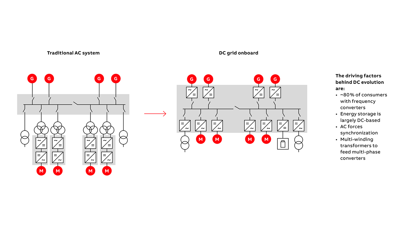
Many salient factors drive the DC distribution evolution onboard nowadays →02:
• Hybrid- and fully electric configurations rely on energy storage systems, eg, batteries that are largely DC-based.
• Most loads require frequency converters, eg, motor supply in which speed is controlled by varying frequency and voltage →02. Typically, frequency converters utilize a double conversion process – use of DC distribution eliminates one of these two conversion stages.
• For AC distribution, multi-phase converters require a supply voltage with a different phase displacement (provided by multi-winding transformers).
• AC distribution forces synchronization (matching frequency, etc.) eg, for generators prior to connection in parallel to the main Bus; and for two sources prior to parallel connection, if a bus-tie must be closed.
Protection is paramount
DC evolution requires advanced protection, whereas for AC distribution systems protection is a snap: The ability to leverage the AC natural zero crossing enables current interruption during normal operating and fault conditions with ease. In contrast, DC interruption is complex during normal operation and during faults. Without the current natural zero crossing, DC current must be forced to zero, eg, by installing circuit breaker poles in series to create a higher arc voltage.
Because AC has been a market standard for so many years, the protection system is well developed and readily available commercially. DC distribution onboard is, by comparison, relatively new and is yet to have the same wide variety of market options available. In addition, chronoamperometric protection selectivity among several protective devices is problematic for DC distribution systems; circuit breakers with electronic trip units would resolve this challenge, yet, few such devices exist for DC distribution.
The trouble with AC distribution
Despite inherent benefits, AC distribution has significant drawbacks: Characteristically, lower power transmission capability result from higher power losses, especially in the presence of a low power factor; this is a major disadvantage of AC distribution. And, with engines operating at a fixed speed because generators have to produce electric energy at a fixed frequency, reduced engine efficiency results. Further, power quality issues are possible due to increased harmonics; the reactive power flow through the whole distribution system must also be managed.
DC distribution wins out
Greater simplicity and higher efficiency highlight DC distribution with easy connection to power sources, eg, battery storage systems, generators; batteries can be directly connected to the main DC bus, or through DC/DC converters; synchronization is unnecessary because generators are connected to the main DC bus by an AC/DC converter via an Insulated Gate Bipolar Transistor (IGBT). Variable frequency generators can be used, which results in fuel savings – the prime mover can work at maximum efficiency. Space is saved too, thanks to the lower volume/weight of high frequency generators and the need for fewer system parts. And, fewer circulating harmonics mean less harmonic issues and better electromagnetic compatibility. Managing reactive power flow is unnecessary. Lower power losses result because a conversion stage to feed variable frequency loads is avoided. These benefits strongly boost the argument in favor of DC distribution.
DC short circuit analysis
With simplicity and efficiency in focus, DC distribution is expedient – as long as protection is suitably handled. Enter ABB to establish a new baseline for DC protection. First, various fault types were evaluated, eg, short circuit and ground fault. ABB analyzed a short circuit on the main DC-bus; the short circuit can be represented by its fault resistance (for short circuit on a feeder too) →03; relevant fault contributions have been considered: DC sources, eg, batteries; DC capacitor discharge, onboard AC generators and AC/DC non-isolated IGBT-based converter →03.
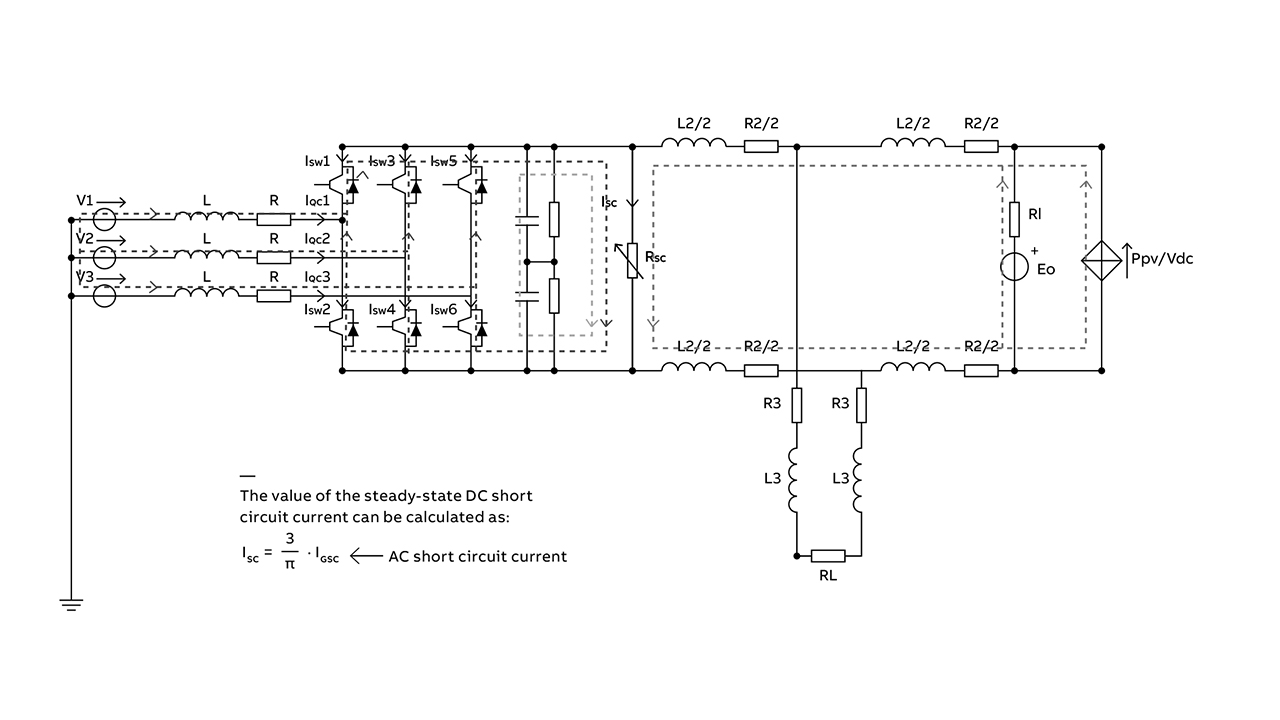
Considering the worst case scenario – a bolted short circuit, it follows that:
• The DC capacitor discharge fault contribution can be high (up to hundreds of kA) also according to cable/busbar impedance among the capacitors and fault location (discharge current peak possibly reached < 1ms).
• Fault contribution from batteries can be high, especially for Li Ion-type batteries, in accordance with the total rated power of the battery system.
• The non-isolated converter cannot limit or interrupt the short circuit current because the current will flow through the freewheeling diodes.
• From the formula given in →03, it follows that the steady-state DC short circuit at the DC converter’s terminals is practically equal to a prospective short-circuit current at the AC converter terminals.
• The higher the number of AC generators in parallel on the DC-bus, the higher the total DC short circuit contribution provided that passes through the converters.
If non-isolated mono- or bidirectional step-up converters (DC bus voltage is higher than DC sources voltage) are installed, they will usually be unable to limit or interrupt the DC source’s fault contribution since the current will flow through the freewheeling diode.Thus, suitable protective devices are required to detect and interrupt the large fault contributions, especially from batteries and the DC capacitor; as well as to protect the converters.
DC ground fault analysis
If the generator neutral point is directly grounded or grounded by a low resistance, the DC active parts are ungrounded while exposed conductive parts are grounded to detect and interrupt a ground fault, even if no one touches the faulty exposed conductive part.
Exposed conductive parts can be grounded using TT or TN systems. In TT systems active parts are grounded, exposed conductive parts are connected to a separated grounding system. Whereas in TN systems: active parts are grounded, exposed conductive parts are connected to the same grounding system. In TT systems, no reclosing path exists for any possible current contribution to the fault by the DC sources; they only feed the load; whereas converters feed the load and ground fault. Contrastingly, in a TN system, a reclosing path exists for the fault current contribution of the DC sources; they feed the load and the ground fault; whereas converters feed only the fault, DC sources feed the fault through the lower IGBTs, while the generators’ contribution passes through the upper freewheeling diodes →04.
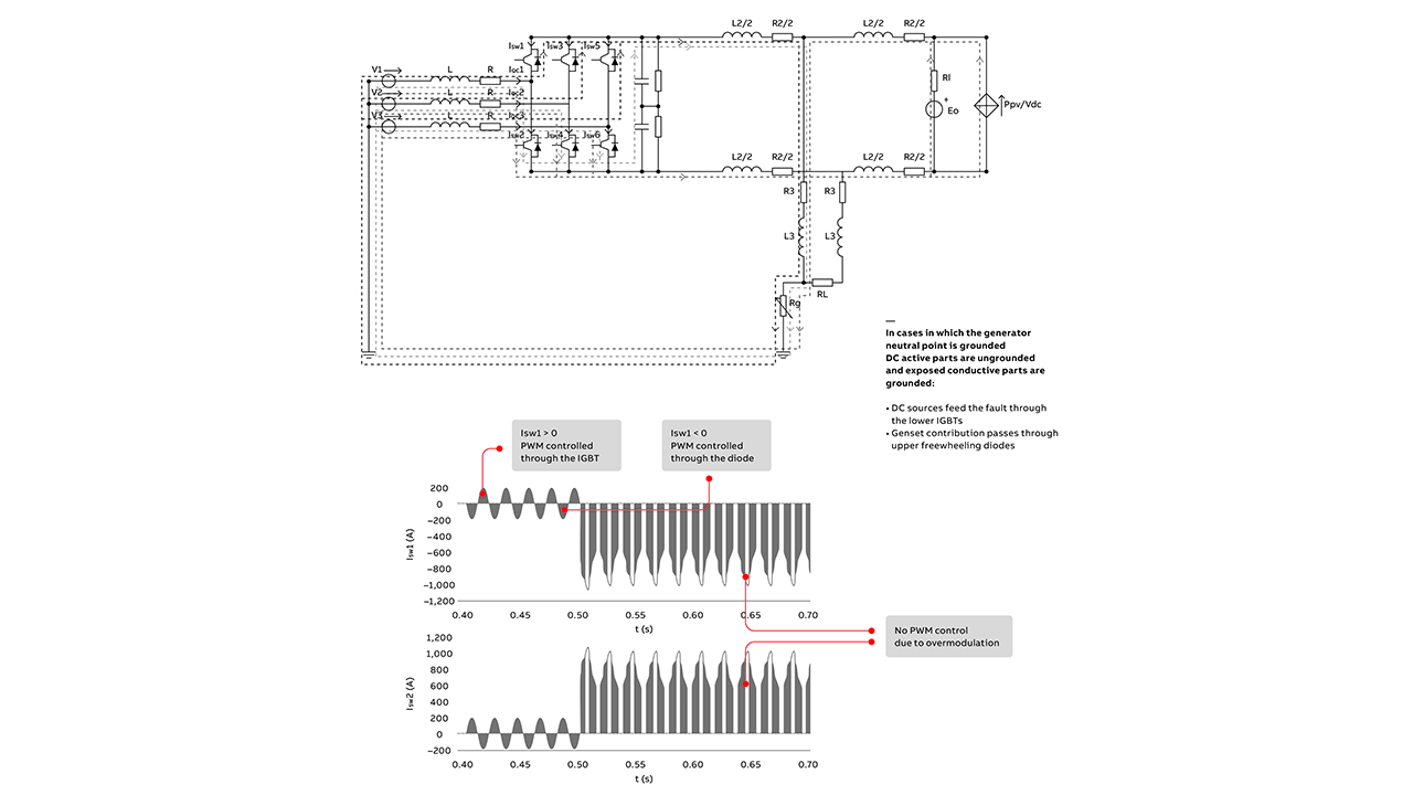
With IGBT embedded protection, the IGBT can be opened automatically whenever the current that is passing through increases above a specific limit →04. Hence, considering the DC ground fault with a TN system it follows that:
• Since the DC sources’ contribution flows only in the lower converter IGBTs, such a contribution can be limited and interrupted thanks to the embedded IGBT protection →05.
• The ground fault current remains high due to the generators’ contribution, which flows through the converter upper freewheeling diodes.
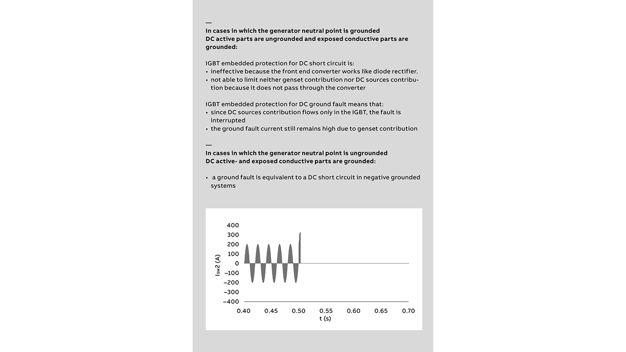
Therefore, suitable protective devices will still be necessary to interrupt the fault contribution provided by the generators, and to protect the converters by a very high interruptive speed.
If the generator neutral point is ungrounded or grounded by a high resistance, the DC active parts and exposed conductive parts are grounded, a ground fault on the positive polarity is equivalent to a DC short circuit from the fault contributions and converter behavior standpoint. Thus, the considerations for the DC short circuit event are also valid for the DC ground fault condition →05.
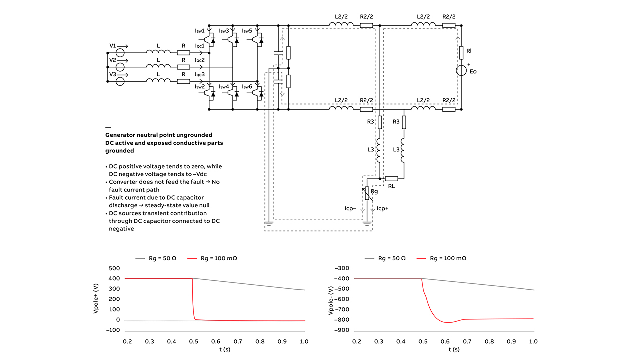
If the generator neutral point is ungrounded or grounded by a high resistance, the DC midpoint and exposed conductive parts are grounded – during a ground fault:
• DC faulty polarity toward ground voltage tends to zero, while DC healthy polarity toward ground voltage tends to minus the rated DC voltage.
• The AC/DC converter does not feed the fault because there is no fault current path.
• High transient DC capacitor discharge contribution exists, but the steady-state value is zero.
• DC sources’ transient contribution through the DC capacitor is connected to healthy polarity.
Nonetheless, the increase of the healthy polarity to ground voltage may create isolation issues. Suitable protective devices are required to detect and interrupt the high DC capacitor discharge current.
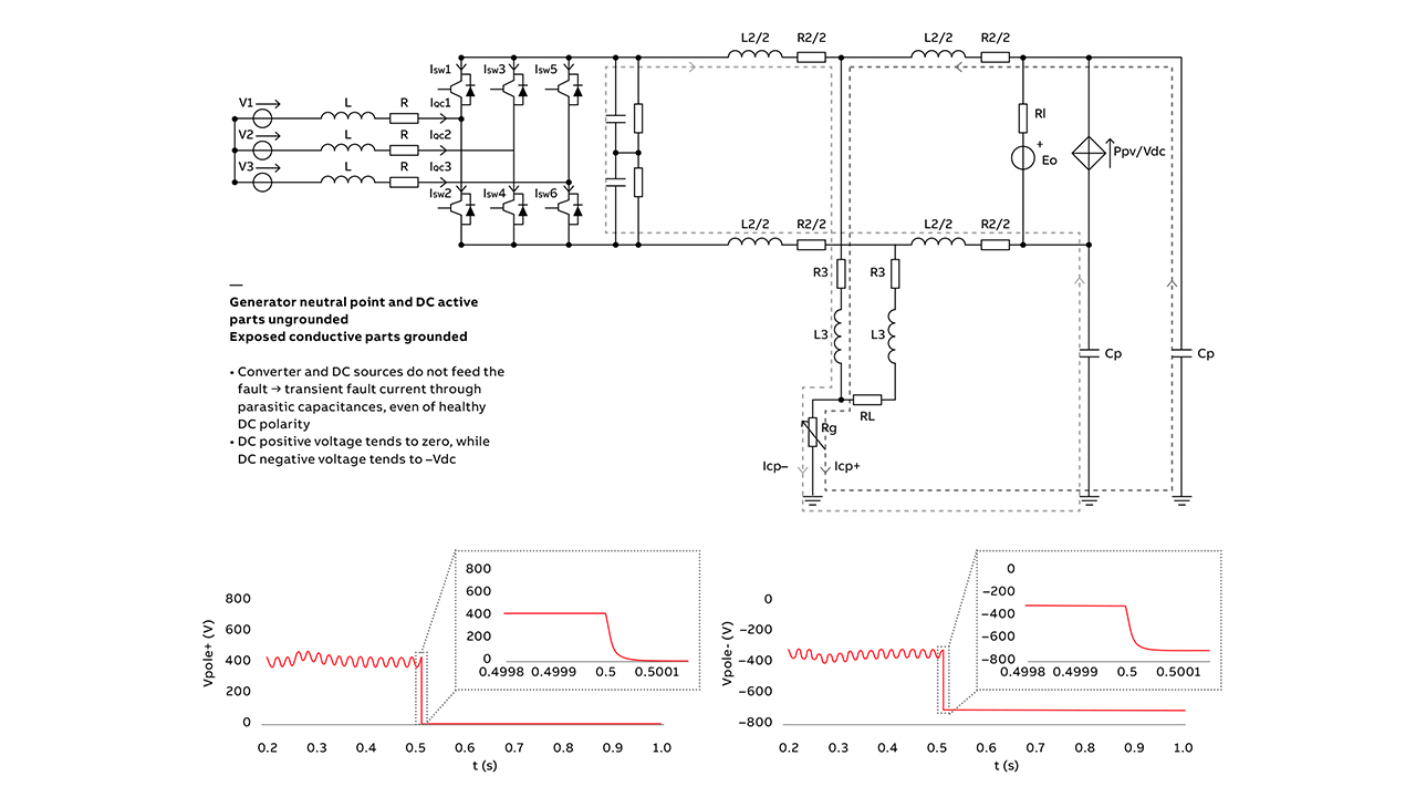
Considering that the generator neutral point and DC active parts are ungrounded or grounded by a high resistance and exposed conductive parts are grounded – during a ground fault →06, it follows that:
• The AC/DC converters and DC sources do not feed the fault →07.
• There is a transient fault current through parasitic capacitances, even when DC polarity is healthy.
• As previously stated, DC faulty polarity toward ground voltage tends to zero, while DC healthy polarity toward ground voltage can vary from half the rated DC voltage value to the whole rated value →07.
Overcoming complex challenges
Based on ABB’s findings, complete fault protection in demanding onboard applications is needed. By combining this knowledge with ideas and analyses, ABB has designed SACE Infinitus →08a, the new circuit breaker with RB-IGCT, a semiconductor technology optimized for a solid-state circuit breaker application capable of reducing losses by up to 70 percent compared to previous technology →08b. SACE Infinitus provides safe, consistent and efficient protection for DC distribution onboard [1], also in the back-to-back configuration for the bus tie circuit breaker application →08c.

08a SACE Infinitus, shown here, is the all-in-one device that provides DC power protection and control. 
08b The SACE Infinitus solid state circuit breaker internal core architecture. 
08c The SACE Infinitus internal core architecture in the back-to-back configuration.
08 The solid state circuit breaker internal core architecture and SACE Infinitus unit are shown.
SACE Infinitus has 1 kVDC rated voltage, 2,500 A frame size and is capable of detecting and isolating the faulty zone completely and safely; clearing the fault rapidly, reducing the negative effects in the faulty area through limitation of the short circuit; and maintaining supply in the non-faulty area. It will also reconfigure the system rapidly to allow the quick resupply of the critical loads.Unlike other breakers, SACE infinitus does not cause efficiency or power losses, and it works well in closed bus-tie configurations. Significantly, the circuit breaker integrates fully with other protection system components and control/management systems. Further, SACE Infinitus is the world’s first solid state circuit breaker to be fully compliant with the strict IEC 60947-2 certification requirements.

With SACE Infinitus, ABB provides marine vessels with a new means to control, protect, and integrate DC network architectures. Providing service continuity and safety in one integrated package with the lowest cost of ownership, this revolutionary solid state circuit breaker is thus helping the shipping industry become more sustainable and energy efficient →09. •
Reference
[1] A. Antoniazzi, et al., “One of a kind”, ABB Review 4/2022, pp. 14 – 19.
