The development of next-generation circuit-breaker drives requires an understanding of mechanical, electrical and magnetic phenomena and their interplay. Cosimulation of these domains leads to speedier development and better drives.
Thorsten Schindler, Arda Tüysüz, Christian Simonidis ABB Corporate Research Ladenburg, Germany, thorsten.schindler@de.abb.com, arda.tueysuez@de.abb.com, christian.simonidis@de.abb.com
Climate change concerns, along with increasing energy demand, are fueling a rapid expansion in generation from renewable energy sources. In fact, wind and solar are the fastest-growing electrical energy sources in the world today. However, the very nature of these energy sources presents challenges for the transmission and distribution grids that they connect to [1] →1. The interruptive nature of, for example, wind and solar energy penetration, obliges transmission and distribution system operators to look for ready solutions and new middle- and long-term strategies.

TenneT in Germany, for example, even today regularly points out the tremendous rise in the number of emergency interventions needed to stabilize the grid [2]. The causes of these interventions are the time-varying energy demand in the south of Germany and, more importantly, the highly stochastic wind energy production in the north of the country and the slow rate of installation of appropriate north-south links.
Qualitative challenges – like the accommodation of more (capacitive) and synchronous switching due to the introduction of more compensation systems, faster and more reliable switching, adaptive travel-curve shaping and recognition – may be faced by electromagnetically driven switchgear. Compared with traditional equipment, such switchgear has fewer parts, simpler mechanical sequences, extremely high reliability and overall quality, very long lifetime and universality of use. For example, ABB’s VM1 medium-voltage (MV) circuit breaker is maintenance-free and can be employed in a wide range of applications: from power stations through controlled distribution in transformer substations to multiple uses by the chemical, steel and automobile industries as well as for power supplies in airports, buildings and the like [3].
![02 VM1 circuit-breaker arrangement [3].](https://resources.news.e.abb.com/images/2019/10/28/0/m8023-02.jpg)
→2,3 shows the arrangement of the VM1 circuit breaker, which consists of a linear electromagnetic actuator, an electronic controller, a capacitor as an intermittent energy source, a main shaft connected to the three vacuum interrupter (VI) poles and several sensors for switch position detection. The overall system has three main parts: the three poles, the linkage to the actuator and the linear magnetic actuator. With the opening and closing coils, opening, closing, latching and releasing can be handled with a single actuator.
![03 VM1 circuit breaker, schematic view [3].](https://resources.news.e.abb.com/images/2019/10/28/0/m8023-03-EN.jpg)
For the closing operation, the actuator needs to provide linear motion to the pushrod within 45 to 60 ms. The counterforce seen by the actuator is the sum of the forces for compressing the contact springs, as well as the inertial forces, projected on the axis of the linear actuator. The primary source of power is a capacitor, precharged to 100 to 400 VDC, which is then applied to the appropriate actuator winding by the electronic controller. The transient nature of the electromagnetic actuator physics means that both the mechanics and the electromagnetics of the system need to be studied to understand the overall operation and to optimize its robust and efficient performance. For this reason, a cosimulation framework for the design of electromagnetic actuators has been developed.
Cosimulation – electromagnetic and mechanic coupling
Usually, for the development of MV actuators, either a simple mechanical model of the linkage and contact separation is inserted into the electromagnetics software tool, or a quasi-static force-over-position curve derived from the ectromagnetics software tool is used with more sophisticated mechanical modelling. However, the use of so-called multibody simulation tools, eg, MSC Adams, and their extension with appropriate deformation, friction and clearance modelling is now indispensable for circuit-breaker development.
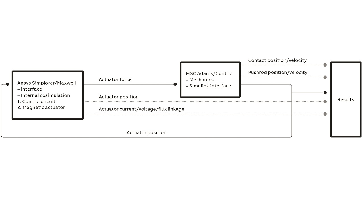
The accurate and robust behavior of circuit breakers is sensitive to the aforementioned mechanisms and neglecting them can give misleading indications. Therefore, a transient cosimulation environment has been introduced in which a time-stepping, quasi-transient electromagnetic finite element method (FEM) model of the actuator is coupled to a multibody mechanical model of the rest of the circuit-breaker system. The FEM actuator model uses Ansys Maxwell electromagnetic field simulation software; the coupling to the multibody mechanical model (which is based on MSC Adams) is done using a combination of Ansys Simplorer, Matlab, Simulink and MSC Adams/Control. Simulink is a graphical programming environment for Matlab; Ansys Simplorer is a multidomain simulation software. An intermediate overview of the cosimulation framework is depicted in →4. Basically, the electromagnetic model feeds the force to the mechanical model, which returns the linear displacement to the electromagnetic model.
MSC Adams – multibody simulation and coupling
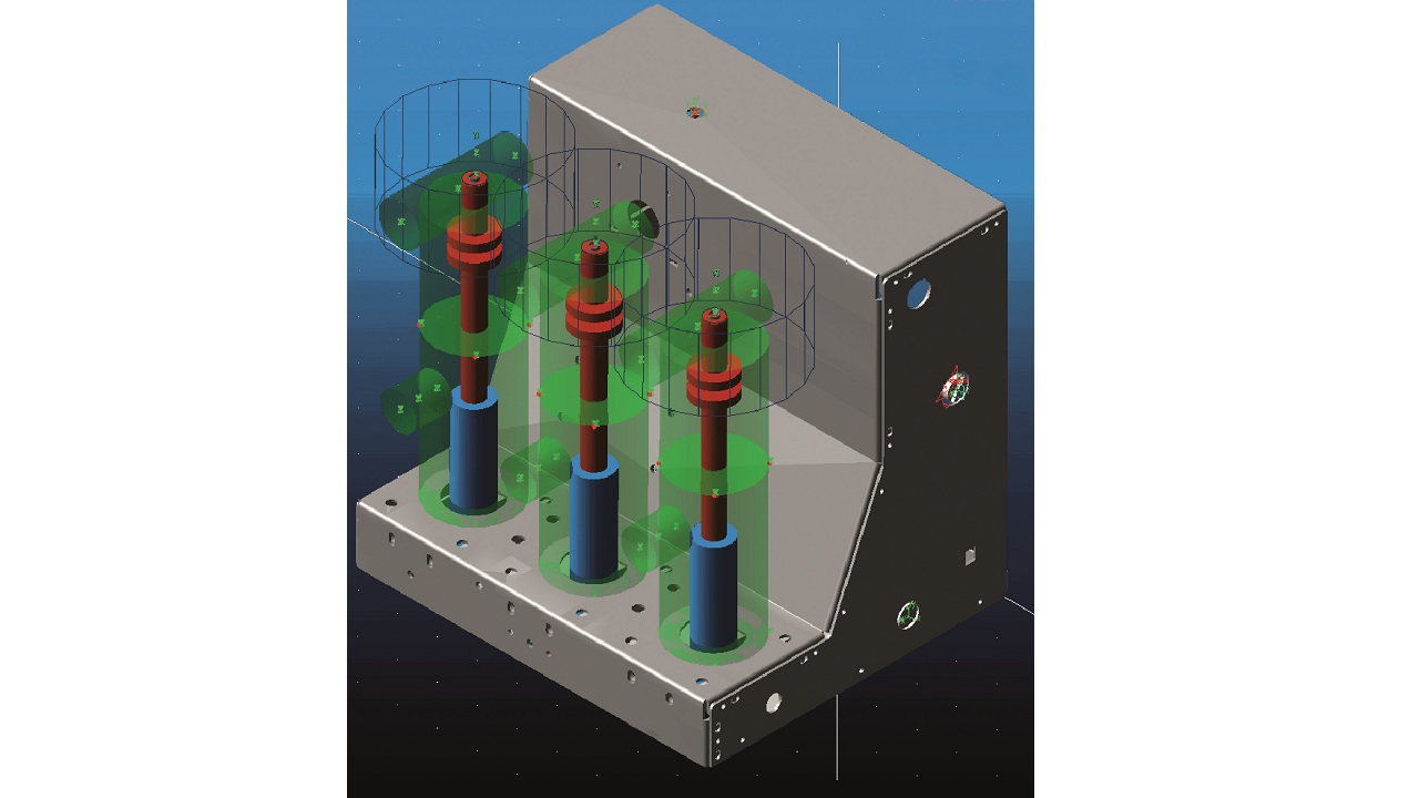
The multibody simulation of circuit breakers must consider sophisticated and systematic modelling of joints with friction and clearance. This modelling is done in, for example, MSC Adams →5. It makes sense to represent models of the poles, linkage and frame parametrically for re-use in a validated library. The physical parameters are taken from the respective real designs.
The final coupling model is achieved via MSC Adams/Control. The input signal is the force variable, the output signal is at least the armature displacement, but the contact gap and velocity of the vacuum interrupter as well as the pushrod position and velocity may also be interesting.
Ansys Maxwell/Simplorer – electromagnetic simulation and coupling
The electromagnetic FEM model of the VM1 actuator is shown in →6. A 2-D model is used to decrease calculation effort while maintaining a good accuracy in terms of modeling the actuator’s performance. Since the coils are wound using a thin wire, skin and proximity effects can be neglected, further simplifying the calculation. On the other hand, even though it makes the numeric solution more demanding, the partial magnetic saturation of the magnetic core is taken into account by using an accurate magnetization curve, since the saturation plays an important role in the actuator’s operation.
![06 Ansys Maxwell – electromagnetic model [3].](https://resources.news.e.abb.com/images/2019/10/28/0/m8023-06.jpg)
The time step size is defined by Ansys Simplorer, including the coupling to MSC Adams. The electromagnetic FEM model (Ansys Maxwell) is inserted as a transient cosimulation block, with Simplorer as the master. For the electrical circuit, it is beneficial to use a state-dependent switch that turns on after the decay of initial vibrations in the mechanical model (to make sure a steady initial state is reached) and turns off at a given value of the total stroke (to provide a basic controllability and limit the energy consumption). A more advanced state-dependent switching may also be implemented with Simplorer for modeling different current controllers and switching patterns, and designing more controllable circuit-breaker drives.
Matlab/Simulink – coupling and postprocessing
The final overview from the viewpoint of Matlab/Simulink is depicted in →7. The cosimulation is started from Matlab for the postprocessing of all interesting variables from electromagnetic and mechanic simulations. Cosimulation ensures that all integration schemes from Ansys Maxwell/Simplorer, MSC Adams and Matlab/Simulink run in parallel with the communication interval specified. In any case, when coupling with Ansys Simplorer, Simplorer will be the master of this top-level cosimulation.
Cosimulation results
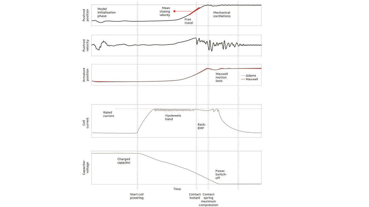
This section discusses typical results from a dynamic cosimulation for a linear electro-magnetic drive.
Dynamic cosimulation extends classic quasi-static precomputation of the actuator force with two phenomena: dynamic coupling and eddy currents, both of which result in additional losses concerning the actuator force level. The realistic force level can only be well represented by the dynamic cosimulation and, depending on the actuator type, may be two to three times smaller than the one proposed by classic quasi-static simulation. As a result, quasi-static simulation overestimates, for example, closing velocities and results in misleading conclusions for the design of electromagnetic actuation of circuit breakers.
Cosimulation for electrical drives
The cosimulation framework for the design of, in particular, electromagnetic actuators for MV circuit breakers has delivered exemplary results. This framework can be easily applied to any kind of electromagnetic and mechanical coupling necessary for the design of electrical drives and may be helpful for the fast and automated development of actuators suited for the requirements of switchgear for the future power grid.
References
[1] Deutsche Energie-Agentur GmbH (dena); dena Ancillary Services Study 2030, “Security and reliability of a power supply with a high percentage of renewable energy,” German Energy Agency Energy Systems and Energy Services, Berlin, 2013.
[2] Focus Online, “Stromnetz unter Druck – Betreiber zahlten 2017 fast eine Milliarde Euro für Noteingriffe.” Available: https://www.focus.de/immobilien/energiesparen/foerderung-in-energiewende-fehlt-stromnetz-unter-druck-betreiber-meldet-rekordkosten-fuer-noteingriffe_id_8180597.html
[3] ABB VM1 product brochure. Available: https://library.e.abb.com/public/e090697e77f9425fbec2337890525a4d/Cat_VM1(EN)M_1VCP000157.pdf