Ondrej Frantisek, Sebastian Breisch ABB Process Automation, Corporate Research Ladenburg, Germany, sebastian.breisch@de.abb.com, ondrej.frantisek@de.abb.com; Alessandro Stucchi, Luciano Chenet ABB SpA Dalmine, Italy, alessandro.stucchi@it.abb.com, francesco.belloni@it.abb.com, luciano.chenet@it.abb.com; Dukkaiappan S. Thevar ABB AG Ratingen, Germany, dukkaiappan.subbiah_thevar@de.abb.com; Markus Schneider, Francesco Belloni Former ABB employees
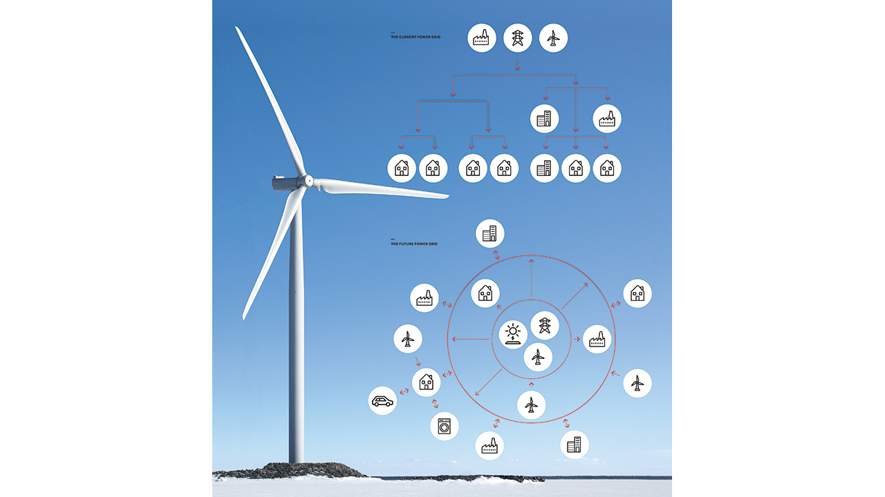
As more renewable energy sources come online, the traditional dominance of centralized utilities diminishes. This shift forces a reconfiguration of the power grid from a pyramid to an interconnected net →01. Further change is driven by the rise of e-mobility and private photovoltaic feed-in to the grid. All this increased complexity places additional demands on the power grid, especially on the devices that protect it, such as vacuum circuit breakers.
The circuit breaker
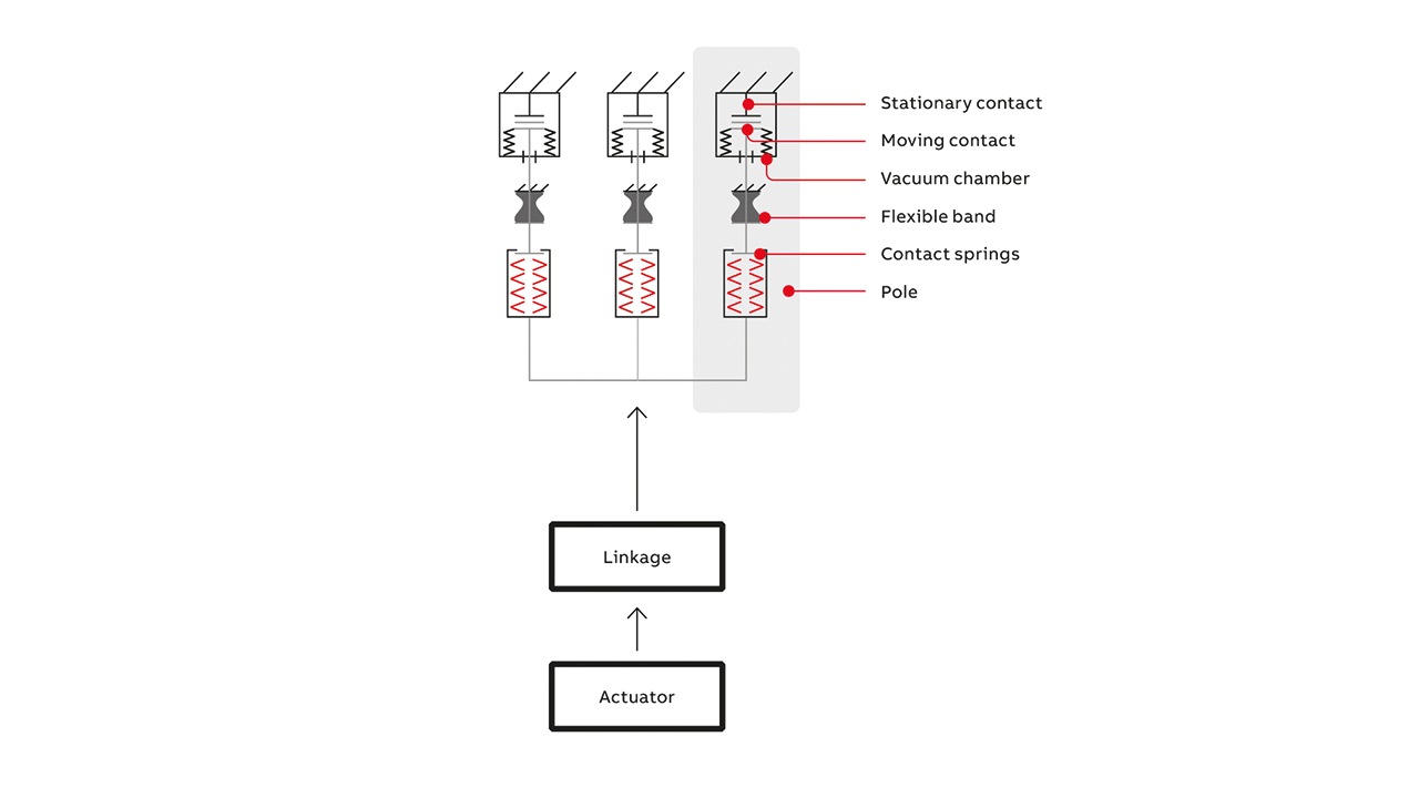
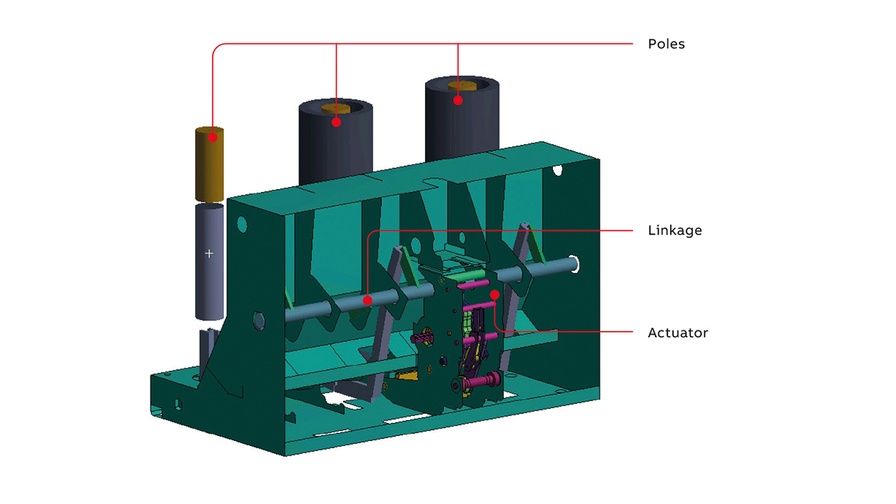
At the heart of the vacuum circuit breaker sit three vacuum chambers (one per phase) that contain moving and stationary contacts. In normal operation, these contacts are closed and pressed together. When a failure occurs, the contacts are separated very quickly to protect the circuit. Reclosing is also fast to prevent an electrical arc igniting and, thus wearing, the contacts.
When closed, the contacts must be pressed together very firmly to minimize electrical resistance at the interface and eliminate the risk of heat welding the contacts together.
Together with these three requirements – high opening and closing speeds and a high contact force in the closed state – it must also be borne in mind that circuit breakers must be able to survive severe operating conditions over tens of thousands of operations. Other requirements also exist, but these will not be discussed here.
Circuit breaker actuator
The circuit breaker is driven by an actuator connected to the three vacuum interrupters by a linkage →02. To attain the high contact speeds and compressions required, high mechanical energy is needed. This energy usually comes from a closing spring. Releasing and stopping this high mechanical energy in combination with the high speeds involved leads to excessive impact loading on the actuator.
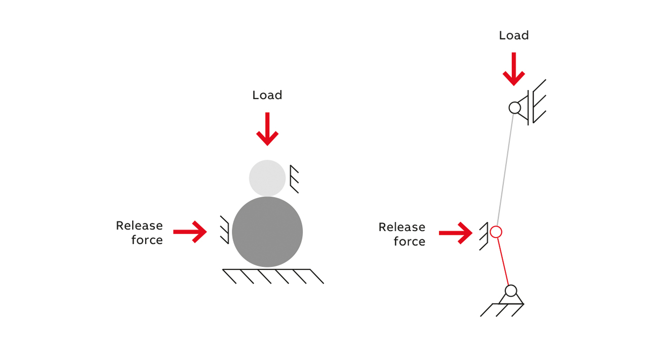
When opening the breaker by pressing the actuator button, the spring force of several kilonewtons must be restored via a finger force of approximately 20 N – a challenging transmission ratio. One way to accomplish such a high transmission ratio is the application of mechanisms in singular positions. When a mechanism is in a singular position (a “singularity”), it can undergo sudden and dramatic change →03. Mechanical actuators in circuit breakers must include several stages of mechanisms close to their singular position to reach the high transmission ratios required. These singularity mechanisms must be geometrically precise, which places demands on assembly and production tolerances, and production methods.
As new grid realities require circuit breakers to operate faster and more often, the question arises as to how new breaker designs can handle faster switching times, higher mechanical impacts and increased frequency of operation →04, →05. And how can these designs be created quickly enough to match the speed of grid transformation? The answer lies with a computer-aided workflow that takes advantage of a combination of modern simulation methods.

Multibody and static approaches
The most straightforward simulation tool available to tackle the breaker design challenge is multibody simulation, which analyzes motion and forces in mechanical systems, including flexible bodies. This tool is useful for initial, rough calculations but is not suitable for the determination of stresses in the circuit breaker actuator. Such stresses can be examined using finite element method (FEM) simulation, which adds deformation and strength data to the information on motion and forces from the multibody methodology.
A dynamic simulation of a circuit breaker is too challenging for FEM simulation but the method is useful for static simulations of critical system situations, for example:
• The circuit breaker with a charged closing spring.
• The beginning of closing, ie, the instant when the closing spring is unlatched and the contacts of poles or linkages are still “blocked” – this is a virtual state that can be imagined as the closing of poles with high inertia.
• The closed circuit breaker.
Though FEM simulation does not describe dynamic behavior or stresses caused by impacts, the method should not be underestimated. For example, it describes well the high-stress state “beginning of closing,” which experience shows to be the critical moment for the lifetime of the majority of the circuit breaker actuator parts. Further advantages are that only the model of the actuator needs to be used, computational times are low and model convergency is feasible.
The method delivers a rough overview of critical spots and an approximate value of stresses. The stresses, however, cannot be used for any fatigue computations.
Dynamic approach
Since circuit breakers are loaded repetitively, a fatigue tool must be used to characterize device endurance. The fatigue tool determines a part’s lifetime – or maximum recommended number of load cycles – based on the stress results from the FEM simulation. However, to simulate such a complex system dynamically as an entire circuit breaker is very difficult and many assumptions and simplifications must be made. For instance, to reach reasonable computation times of some days, parts must be meshed very coarsely. Roughly discretized parts of the dynamic systems describe sufficiently the dominant and most important loading effects – for instance, first bending and torsional modes.
Stress value results are, however, inferior for roughly meshed parts – a serious issue as the error in lifetime estimation can be an order of magnitude higher than the error in stresses. In other words, the stresses from a roughly meshed global dynamic model cannot be considered for further fatigue post-processing. Another idea would be to mesh the global dynamic model finely enough to use stresses in a fatigue tool. This approach is impracticable for many reasons.
The individual deficiencies of the multibody, FEM and dynamic approaches described are the main reasons why a workflow for endurance prediction of circuit breaker parts that combines these techniques in a novel way had to be developed.
Novel workflow for endurance prediction of circuit breaker parts
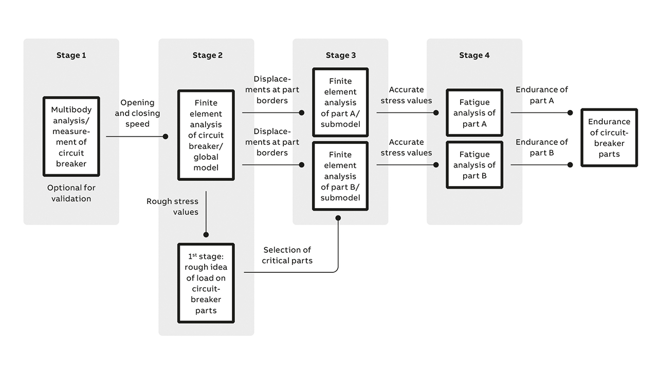
The novel workflow’s target is to largely overcome the disadvantages of the approaches described so far by utilizing a creative combination of the simulation tools described above. The first, optional, stage sees a reference model or set of measurements generated from a multibody analysis →06. Since the most important global kinematic factors influencing stress values are closing and opening speeds, the values of these parameters generated here should be used for validation in stage two – preparing the global dynamic model of the entire circuit breaker. This stage is the most critical in the novel workflow.
In stage two, the farther a point is from the locality of interest, the coarser is the mesh chosen there. Mesh coarseness is selected so the calculation only just converges. A rough mesh is usually sufficient for a good deformation description, as illustrated in →07. In this example, the point of interest is the actuator, so the linkage (actually, its housing) is simulated by just a shell element whereas the actuator is modeled by solid elements.
This method allows adequate deformation and motion to be observed, specifically around joints. The rough stress values indicate critical parts worthy of further examination.
In stage three, submodels of the critical parts are run with improved discretization. A simple copy of the global model is enough. Irrelevant parts are suppressed and only critical parts and their neighbors are used for simulation. Waveforms of the joint coordinates are applied to the parts neighboring them as application of these waveforms too close to the critical areas produces inaccuracies. There are as many submodels as critical parts and the submodels must have a mesh finer than the global model. The result of stage three is a precise stress field mapping of critical parts over time.
Stage four is the post-processing of stress values in a fatigue module. Stress waveforms must be imported as time functions since the associated parts are loaded many times in many different directions during circuit breaker operation, which results in many stress peaks, all of which contribute to part fatigue.
The result of these four stages is the number of operations the circuit breaker will be capable of and the lifetime of each of its parts.
Keeping up with a changing grid
Combining simulation tools in the manner described speeds the development path for vacuum circuit breakers, allowing the rapid creation of new designs of this complex device that can handle the increased demands placed on them by the shifting power grid landscape. The novel workflow results in a model that is roughly discretized in some places and finely in others. This approach offers a low computational time and ample opportunity for multiple model runs. Despite the roughness of some parts of the model, the predictions of lifetimes were very precise when verified by comparison with tests. Presentation of the comparison in detail would exceed the scope of this article, but will form part of a future publication.
