Maren Hansen, Management Trainee, ABB Marine & Ports
Tomas Tengner, Global Product Specialist, Energy Storage, ABB Marine & Ports
Frank Wendt, Senior Engineer, ABB Marine & Ports
Introduction
Vessel-based power systems often come with highly dynamic load profiles, and this is especially true for icebreakers. Traditionally, dynamic load is met by oversized generators running on fossil fuel, which leads to inefficient operation during periods of low demand.
The icebreaker Polaris has been operating for three winter seasons in the Bay of Bothnia. ABB has conducted a study to investigate how an energy storage system could improve the environmental footprint of the vessel while improving fuel efficiency and dynamic response.
Key findings from this study include the following simulation results for one day, assuming an onboard hybrid battery system:
- For one representative day with LNG operation: 32% CH4 reduction, 12% less fuel consumption and 46% reduction in engine hours
- For one representative day with diesel operation: 6% reduction in fuel consumption, 36% reduction of engine hours.
The vessel
Polaris is the world’s first LNG-powered icebreaker. The vessel is owned and operated by Arctia Ltd, a Finnish state-owned company. Polaris is built primarily for assistance services in the Baltic Sea, in addition to oil spill response operations.
The vessel is equipped with four Low Pressure Dual Fuel (LPDF) engine driven gensets, with an auxiliary engine for producing electricity when the vessel is in port. The electrical power plant’s combined output is 22,5 MW. The propulsion system consists of three ABB Azipod® units, two 6,5 MW stern units and one 6 MW bow unit, as shown in Figure 1.

Figure 1: Single line diagram for Polaris With a length of 110 m, and a capability to open a uniform ice-free channel through ice field with thickness 1,8 m, Polaris is the most powerful Finnish icebreaking vessel ever constructed.
Environmental challenges of LPDF engines
Stricter emissions regulations for different greenhouse gases (GHG) are leading ship owners to take action. Using LNG as a main fuel is trending as a response to restrictions on NOx and CO2 emissions, with low-pressure dual fuel (LPDF) engines as a popular choice. [1]
However, one main drawback of LPDF engines, especially when running on gas, is their substantial level of methane slip. Methane slip is the release of unburnt methane caused by incomplete combustion.
According to a measurement study[2], Methane slip comprises 92-97% of measured THC emission in LPDF engines. Emissions data available for methane are relatively consistent down to 50% load. For the current study, the available data is interpolated as shown in Figure 2, and used as a basis for calculation.
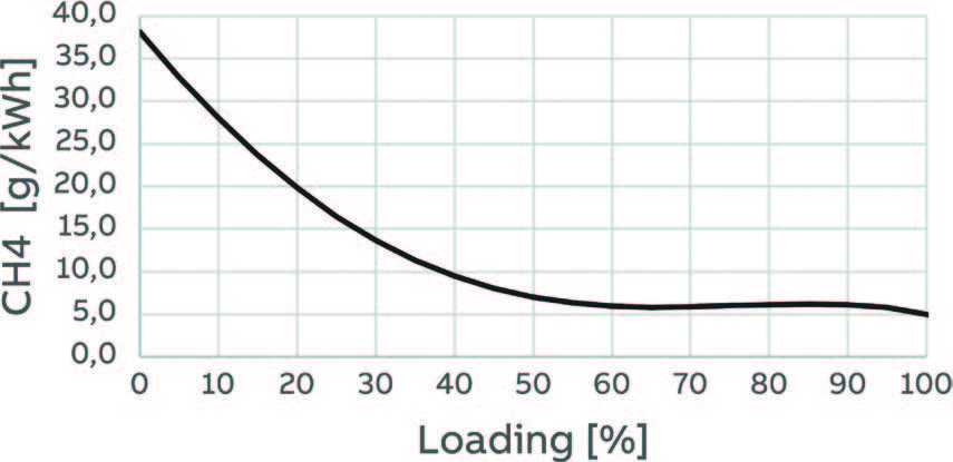
As seen in Figure 2, the challenges associated with methane slip increase at low load operation, as a consequence of poor fuel utilization due to low operational fuel-to-air ratios.
This is an underlying problem in the industry, as CH4 has a GWP of 25 (25 times higher than CO2)[3] yet there is no standard regulating methane slip for marine gas engines. However, concerns associated with the environmental effect of methane have lead to increased focus on the issue.
Scope of work
Installation of an energy storage system could contribute to reducing total GHG emissions, primarily CH4, in addition to reducing fuel consumption and improving the dynamic performance of the system.
In this work, a Matlab file was programmed to investigate the effect of installing energy storage onboard Polaris. The work is based on operational data presented in the following section.
The overall objective was to simulate a battery system that can absorb large load variations and hence improve fuel efficiency and ramping capability.
Conditions of operation
Polaris is designed for four continuous weeks at sea, though the normal crew change interval is 10 days.
During operation in the Bay of Bothnia, IB Polaris was equipped with an Azipod® ice load measuring system to determine load levels. During the period from January 2017 to May 2019, around 7400 hours were recorded, and about 4,000 hours of operation observed.
For the case study, load measurements for two days have been extracted; one day for diesel operation and one day for gas operation.

Combining the ship log and the load profile in Figures 3 and 4, the following conclusions are evident:
- The generators are mainly loaded by the Azipod® propulsion (as expected) with approximately 200kW vessel hotel load (pumps, fans, light etc.)
- Large load fluctuations during icebreaking
- Large increase in power consumption during assistance
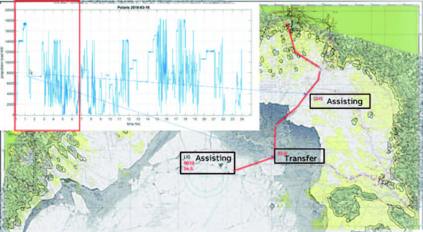
According to Mr. Sampo Viheriälehto, a Master Mariner with extensive experience in operating the Finnish icebreakers, load fluctuations are caused by the control levers being used actively, and the magnitude of the variations depends on the thickness and resistance of the ice. Another key aspect is the fact that the distance between Icebreaker and assisted vessel should be adjusted according to ice and weather conditions and the performance of the assisted vessel. This distance may be as little as only a few meters, but could also be up to several hundred meters.

On 09.02.2018, Polaris was mainly fueled by LNG. Only 23 hours of operation were available for the day, as presented in Figure 5. For LNG operation the engines do not allow for fast load changes and have an even slower response compared to diesel. As a consequence the performance of the vessel is slower when running on LNG compared to diesel.
Modelling and simulation
The system and preconditions
The hybrid power system in the model consists of four main generators (the auxiliary generator is excluded), one battery and one main system load, as shown in Figure 6. The battery is charged from the generators, since the vessel usually does not operate close to a harbor. It is worth mentioning that the model is simplified and cannot embody the full complexity of the power system onboard Polaris.

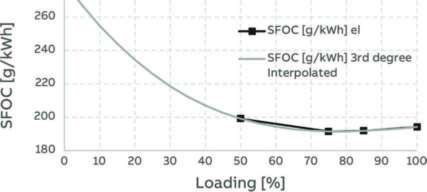
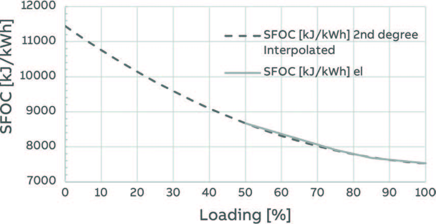
The gensets are based on characteristics of dual-fuel engines. They can be operated in gas mode or in diesel mode, and the fuel consumption is assumed to follow the SFOC curves shown in Figures 7 and 8 for diesel and LNG, respectively. The Figures are adjusted for genset efficiency and interpolated for loading lower than 50%.
Impact of load dynamics
As seen in figures 7 and 8, fuel consumption increases substantially during low load. Another aspect is the dynamics of the load. A commonly held belief is that having high ramp rates on generator loading negatively affects both the fuel efficiency and the release of greenhouse gasses. Accellerating the engines occurs with lower efficiency and leads to incomplete combustion. There is limited available validated data to quantify this, but based on internal estimates and experiences, a linear correlation between load fluctiations, fuel efficiency and CH4 emissions has been assumed, resulting in an added penalty for dP/dt on both fuel consumptipon and CH4 emissions. Maximum limitations are set for load gradient 0.33% /s with corresponding penalities of 10% fuel increase and 20% CH4 increase.
Selection of energy storage system
The analysis is based on a JP3 battery cell, and the design of the controller is based on a fixed energy storage dimension. The size was selected by means of iteration, as illustrated in figure below, to simulate the dynamic behavior of the gensets.

Controller design
The simulation model has two tuning parameters: battery capacity and max ramp rate. The battery acts as a peak shaving unit and the ramp rate limiting function limits the dynamic components of the load. A simplified flow chart of the control strategy is shown in figure 10.

Results and discussion
16.03.2018 (diesel)


09.02.2018

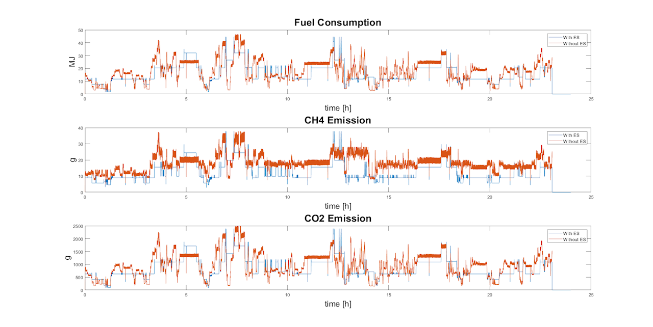
The simulation resulted in the following savings for the two respective days:
LNG operation:
- CH4 reduction: 32%
- Fuel reduction: 12%
- Engine hour reduction: 46%
Diesel operation:
- Engine hour reduction: 36%
- Fuel reduction: 6%
The simulation of the power system shows how an energy storage system can contribute to supply power peaks during periods of high demand, as well as absorbing load fluctuations. These aspects appear to pay off especially in terms of reduced CH4 emissions.
The large decrease in engine hours can also be seen as direct savings in terms of maintenance costs.
Installation of energy storage can also improve the dynamic performance of the system, which may have great significance for an icebreaker. Exact quantification of the performance improvement is excluded from the analysis, as slow engine speed already limits the load profile used in the simulation. Energy storage can nevertheless provide instantaneous power and hence also provide ramps where the engines fall short. The figure below illustrates how a battery can absorb load fluctuations that are faster than a selected range, below simulated for the range 200 kW/s

Simulation shows reduction potential for both fuel consumption and CH4 emissions when gensets are operating more efficiently, and when the dynamics of the load are decreased. High ramp rates on generator loading are known to affect fuel efficiency negatively, but there is limited data to quantify this. It may therefore be reasonable to believe that savings potential is even greater in the transformation to a more stable load profile. This could be the subject of further study.
Spinning reserve
As the minimum State of Charge (SOC) is set to 20% of installed capacity, there will always be a certain amount of energy available in case of a generation outage. The range of SOC can consequently be adjusted accordingly. This contributes to increasing redundancy and can allow generators to work at optimum power output, without the need to keep additional genset capacity for spinning reserves.
The impact of battery choice
A larger battery could provide more savings for two reasons: more efficient energy management system, and lower losses due to lower c-rate. A battery cell with enhanced cycle life and charge and discharge capability could on the other hand enable a smaller battery. Depending on the choice of battery and the control strategy, an energy storage system could be optimized further in terms of sizing, as a trade-off between cost and performance.
Conclusion and next steps
Despite the limitations of the model, it is evident from the simulations that installing a battery can play a positive role in the power system of Polaris. In particular, reduction of both methane slip and the number of running hours on the engines should be emphasized. Next steps that could be further developed include:
- Quantifying the actual impact of dynamic load
- Tuning of the optimal energy storage system solution
[1] Methane slip from gas fueled ships: a comprehensive summary based on measurement data
[2] Methane slip from gas fueled ships: a comprehensive summary based on measurement data
[3] https://www.epa.gov/ghgemissions/overview-greenhouse-gases#CH4-reference
Litterature:
Optimal Operation and Sizing of Energy Storage System for a Ship Electrical Power System
Methane slip from gas fueled ships: a comprehensive summary based on measurement data
Findings revised as of November 2020 due to an updated model.